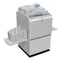
MAIN DRIVE AND IMAGE UP/DOWN SHIFTING DRIVE SECTION
SM 3-137 C262/C265
Replacement
Adjustment
Finishing
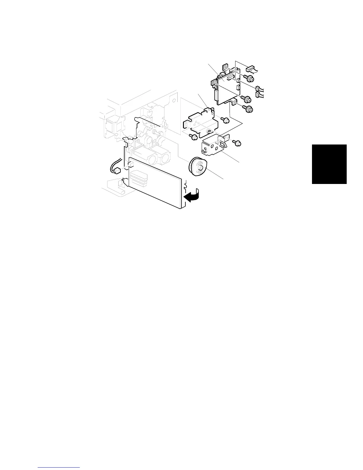
1. Install the registration roller lifting cam [A]. ( 3.9.13 Registration roller lifting
cam Position Adjustment for the correct position of the cam.)
2. Install the lifting cam bracket [B], the motor cover [C], and the double feed
detector board [D]
3. Install the exit pawl, and adjust the paper exit pawl drive timing. ( 3.12.6
Paper exit pawl drive timing adjustment.)
4. Adjust the pressure cylinder rotation knob. ( 3.11.4 Pressure cylinder
rotation knob adjustment.)
5. Remove all special tools (the drum drive-securing tool and two positioning
shafts).
6. Adjust the gap between the exit pawl and the drum. Also adjust the gap
between the paper scraper and the pressure cylinder. ( 3.12.5 Gap
adjustment between paper pick-off plate and pressure cylinder and 3.12.7
Gap adjustment between exit pawl and drum.)
7. Install the printing pressure shift cam unit. ( 3.12.3)
8. Install the air knife fan unit. ( 3.12.2)
9. Install the paper delivery unit. ( 3.12.2)
10. Install the paper delivery cover. ( 3.12.2)
11. Install the knob. ( 3.2.1)
12. Install the left cover. ( 3.2.2)
13. Install the front cover, inner cover and knob cover ( 3.2.1)
C262R142.WMF
[A]
[C]
[B]
[D]