Detailed description
2.6 Interface structure
Basic logic functions: PLC Basic program powerline (P3 pl)
Function Manual, 11/2006, 6FC5397-0BP10-2BA0
41
'%
%\WH
00&
0&3
%3
%3
06)
GLVWULEXWRU
1&
FKDQQHO
067'(+
)YDOXHV
&RQWURO
VLJQDOV
6WDWXVVLJQDOV
3URWHFWLRQ]RQHV
$FWLYDWLRQRI
SURWHFWLRQ]RQHV
$X[LOLDU\*DFWLRQV
6WDWXVVLJQDOV
$[LVVSLQGOH
LQWHUIDFH
*JURXS
GHFRGHUV
23VLJQDO
MXPSHULQJ
0GHFRGHU
$FWLYH*IXQFWLRQV
'HFRGHG0VLJQDOV
00
$X[LOLDU\IXQFWLRQ
FKDQJHVLJQDOV
*(2D[HVVWDWXV
3URJUDPFKDQQHO
VWDWXV
3URJUDPFRQWURORI
00&
*(2D[HV
7UDYHUVHVLJQDOV
3URJUDP
FRQWURO
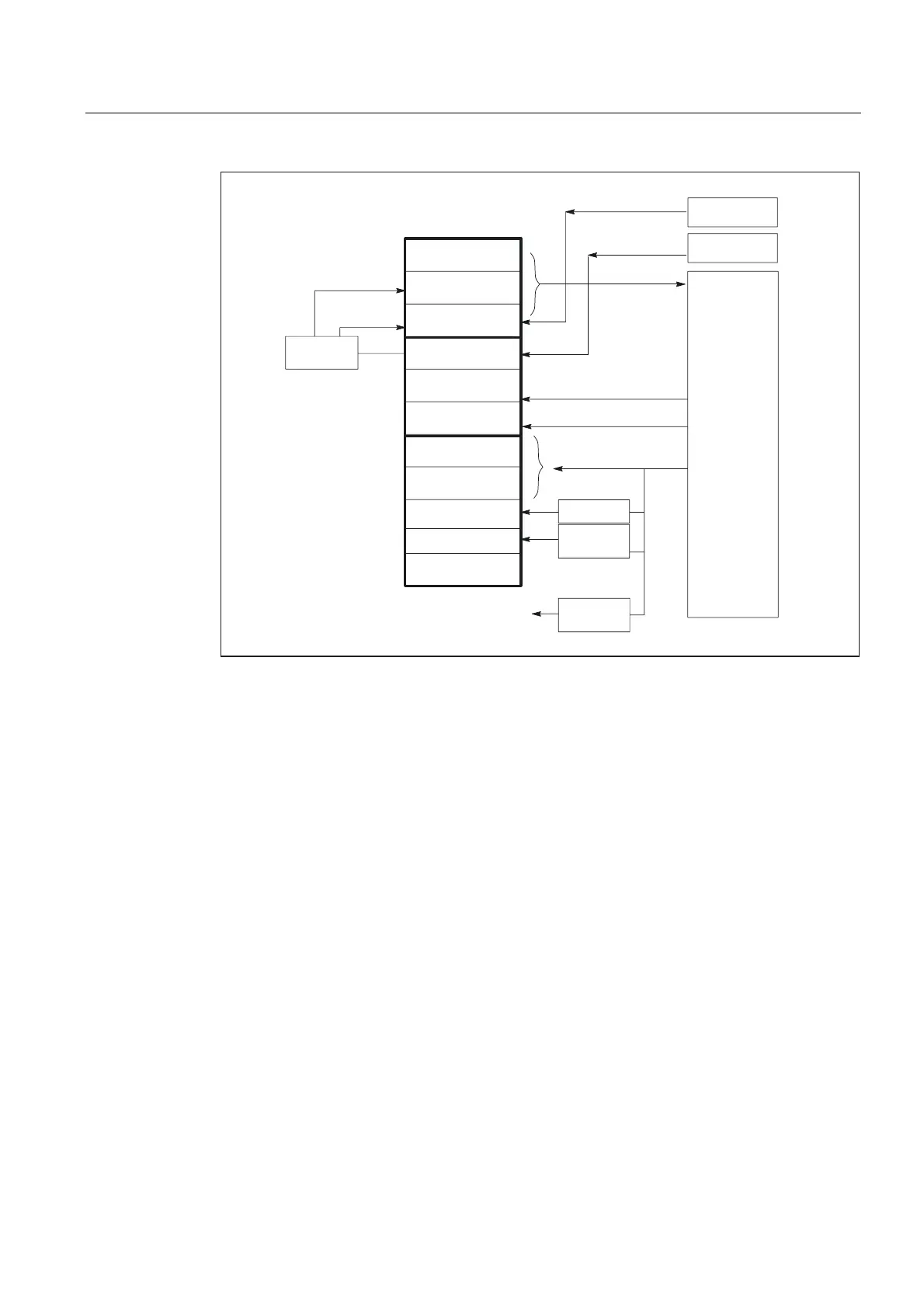
Figure 2-6 PLC/NC channel interface
PLC/axis, spindle, drive signals
The axis-specific and spindle-specific signals are divided into the following groups:
• Shared axis/spindle signals
• Axis signals
• Spindle signals
• Drive signals
The signals are transmitted cyclically at the start of OB1 with the following exceptions:
Exceptions include:
INC-Mode of HMI, axial F-value, M-/S-value
.
An axial F value is entered via the M, S, F distributor of the basic program if it is transferred
to the PLC during the NC machining process.
The M and S value are also entered via the M, S, F distributor of the basic program if an S
value requires processing together with the corresponding M value (M03, M04, M05).
 Loading...


