Detailed description
2.1 Axes
Basic logic functions: Axes, coordinate systems, frames (K2)
Function Manual, 11/2006, 6FC5397-0BP10-2BA0
29
2.1.11 Axis configuration
Allocation
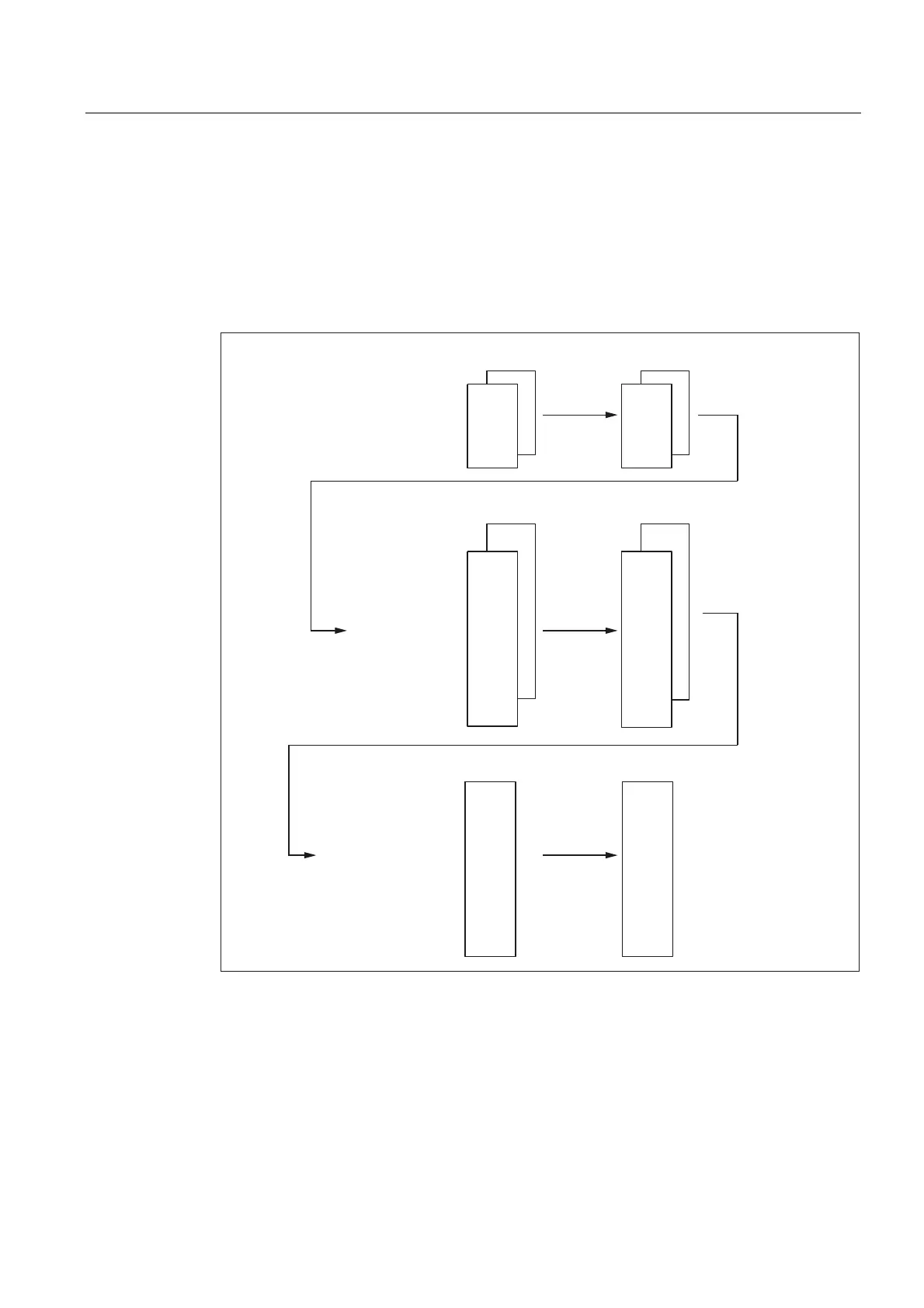
The figure below shows the assignment between the geometry axes, special axes, channel
axes and machine axes as well as the names of the individual axis types. MD are used for
assignment.
&KDQQHO
&KDQQHO
JHRPHWU\D[LV>@
JHRPHWU\D[LV>@
JHRPHWU\D[LV>@
&KDQQHO
&KDQQHO
&KDQQHO
&KDQQHO
FKDQQHOD[LV>@
FKDQQHOD[LV>@
FKDQQHOD[LV>@
FKDQQHOD[LV>@
FKDQQHOD[LV>@
FKDQQHOD[LV>@
FKDQQHOD[LV>@
FKDQQHOD[LV>@
&KDQQHO
&KDQQHO
PDFKLQHD[LV>@
PDFKLQHD[LV>@
PDFKLQHD[LV>@
PDFKLQHD[LV>@
PDFKLQHD[LV>@
PDFKLQHD[LV>@
PDFKLQHD[LV>@
PDFKLQHD[LV>@
0'01B$;&21)B0$&+$;B1$0(B7$%
0'0$B63,1'B$66,*1B72B0$&+$;
&
:
%
=
<
;
0'0&B$;&21)B&+$1$;B1$0(B7$% 0'0&B$;&21)B0$&+$;B86('
0'0&B$;&21)B*(2$;B$66,*1B7$%0'0&B$;&21)B*(2$;B1$0(B7$%
&
:=0
%
=
<
;
=
<
;
Figure 2-4 Axis configuration
 Loading...


