Detailed Description
2.3 Tool cutting edge
Basic logic functions: Tool Offset (W1)
44 Function Manual, 11/2006, 6FC5397-0BP10-2BA0
2.3.5 Geometry tool radius compensation (tool parameters 6 to 11)
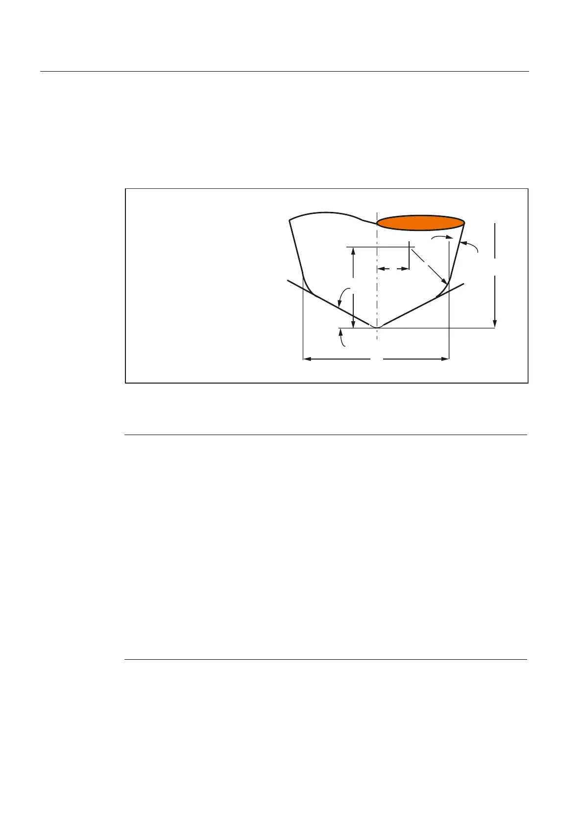
Tool geometry
Geometry tool radius compensation defines the shape of the tool.
G
K
E
H
D
U
I
KWRROOHQJWK
7RRO3IOHQJWK
7RRO3HOHQJWK
7RRO3GUDGLXV
7RRO3UUDGLXV
7RRO3DDQJOH
7RRO3EDQJOH
Figure 2-10 Description of the tool geometry
Note
The tool description as given in the figure is required only for 3D face milling.
References:
/PGA/ Job Planning Programming Manual Transformations,
Section: Three-, four- and five-fold transformations (TRAORI)
Otherwise,
On SINUMERIK 840D/810D, only tool parameter 6 (tool radius 1) is used as standard from
tool parameters 6 to 11. For 2D TRC with contour tools, additionally to the tool parameters
10 and 11, a minimum or maximum limit angle can be defined for the cutting edge
compensation when using multiple tool cutting edges.
Please refer to the following documentation for information about entering tool shapes
(radius for tool radius compensation) in tool parameters 6 to 11 and how these are
calculated by tool radius compensation in the three geometry axes:
References:
/PA/ Programming Manual Fundamentals; Tool Compensations,
Section: 2½ D-tool compensation
/FB3/ Function Manual Special Functions; 3D Tool Radius Compensation (W5)
 Loading...


