Detailed Description
2.9 Sum offsets and setup offsets
Basic logic functions: Tool Offset (W1)
162 Function Manual, 11/2006, 6FC5397-0BP10-2BA0
7RROFDUULHU
WRROFRPSRQHQW
7RRO
.LQHPDWLFWUDQVIRUPDWLRQ
WRROFRPSRQHQW
.LQHPDWLFWUDQVIRUPDWLRQ
ZRUNSLHFHWDEOHRUSDUWFRPSRQHQW
:&6
%&6
7&6
0&6
.&6
3
;
=
;
=
;
=
;
=
;
=
.
7
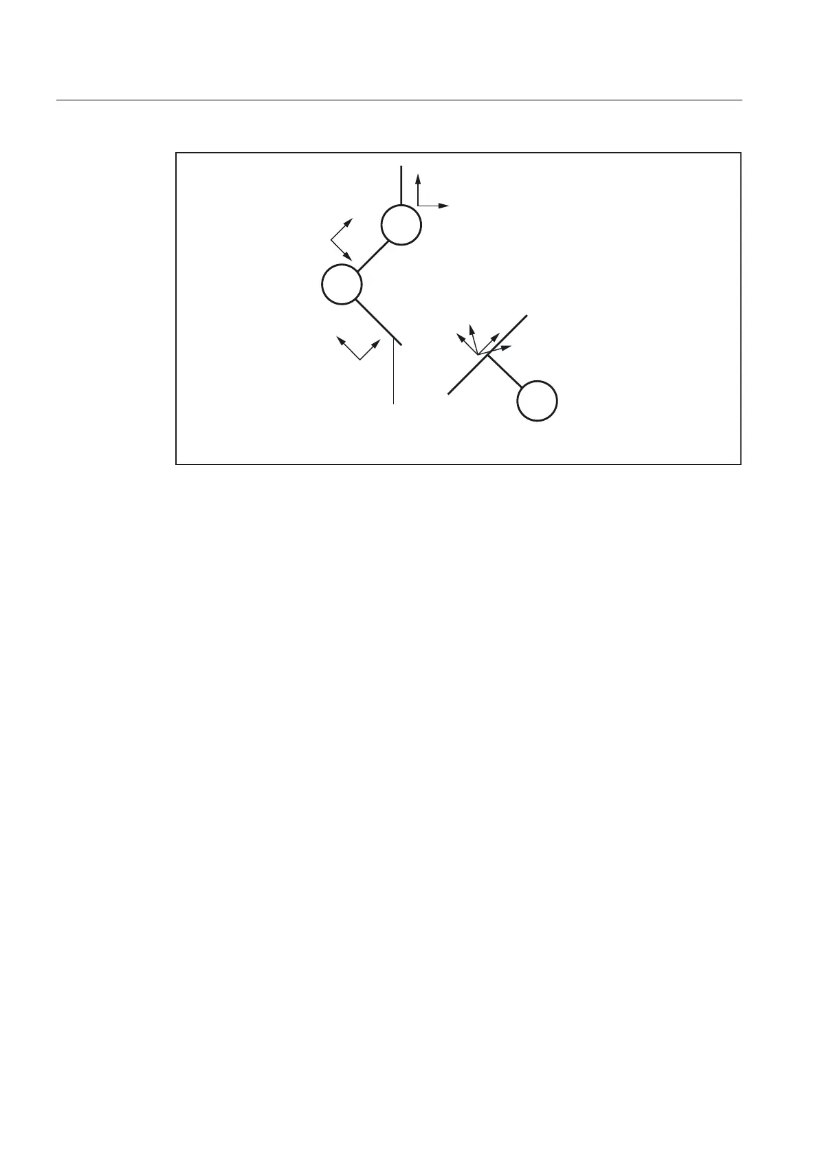
Figure 2-53 Coordinate system for the evaluation of tool lengths
2.9.5.2 Functionality of the individual wear values
TOWSTD
Initial setting (default behavior):
• The wear values are added to the other tool length components.
The resulting total tool length is then used in further calculations.
In the case of an active toolholder with orientation capability:
• The wear values are subjected to the appropriate rotation.
TOWMCS
Wear data in the MCS (machine coordinate system):
In the case of an active rotation by means of a toolholder with orientation capability:
• The toolholder only rotates the vector of the resultant tool length. Wear is ignored.
Then the tool length vector rotated in this way and the wear are added. The wear is not
subjected to the rotation.
If no toolholder with orientation capability is active or this does not result in a rotation,
TOWMCS and TOWSTD are identical.
 Loading...


