Detailed description
2.7 Structure and functions of the basic program
Basic logic functions: PLC Basic program powerline (P3 pl)
Function Manual, 11/2006, 6FC5397-0BP10-2BA0
59
2.7.8 Symbolic programming of user program with interface DB
General
Note
The files NST_UDT.AWL and TM_UDT.AWL are supplied with the PLC basic program.
The compiled UDT blocks from these two files are stored in the CPU program of the basic
program.
A UDT is a data type defined by the user that can, for example, be assigned to a data block
generated in the CPU.
Symbolic names of virtually all the interface signals are defined in these UDT blocks.
The UDT numbers 2, 10, 11, 19, 21, 31, 71, 72, 73 are used.
The assignments have been made as follows:
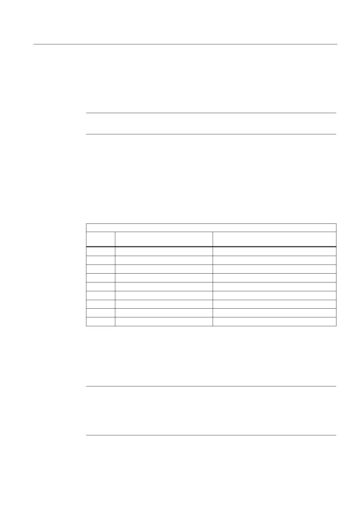
UDT assignments
UDT
number
Assignment to interface DB Description
UDT2 DB 2 Alarms/messages
UDT10 DB10 NCK signals
UDT11 DB11 Mode group signals
UDT19 DB19 HMI signals
UDT21 DB21 to DB30 Channel signal
UDT31 DB31 to DB61 Axis/spindle signals
UDT71 DB71 Tool management: Load/unload locations
UDT72 DB72 Tool management: Change in spindle
UDT3 DB73 Tool management: Change in revolver
To symbolically program the interface signals, the interface data blocks must first be
symbolically assigned using the symbol editor.
For example, symbol "AxisX" is assigned to operand DB31 with data type UDT31 in the
symbol file.
After this input, the STEP 7 program can be programmed in symbols for this interface.
Note
Programs generated with an earlier software version that utilize the interface DBs described
above can also be converted into symbol programs. To do so, however, a fully qualified
instruction is needed for data access in the earlier program (e.g., "U DB31.DBX 60.0" - this
command is converted to "AxisX.E_SpKA" when the symbols function is activated in the
editor).
 Loading...


