Detailed Description
2.2 Axis monitoring, protection zones (A3)
Basic logic functions: NC/PLC interface signals (Z1)
Function Manual, 11/2006, 6FC5397-0BP10-2BA0
67
2.2.3 Signals to axis/spindle (DB31, ...)
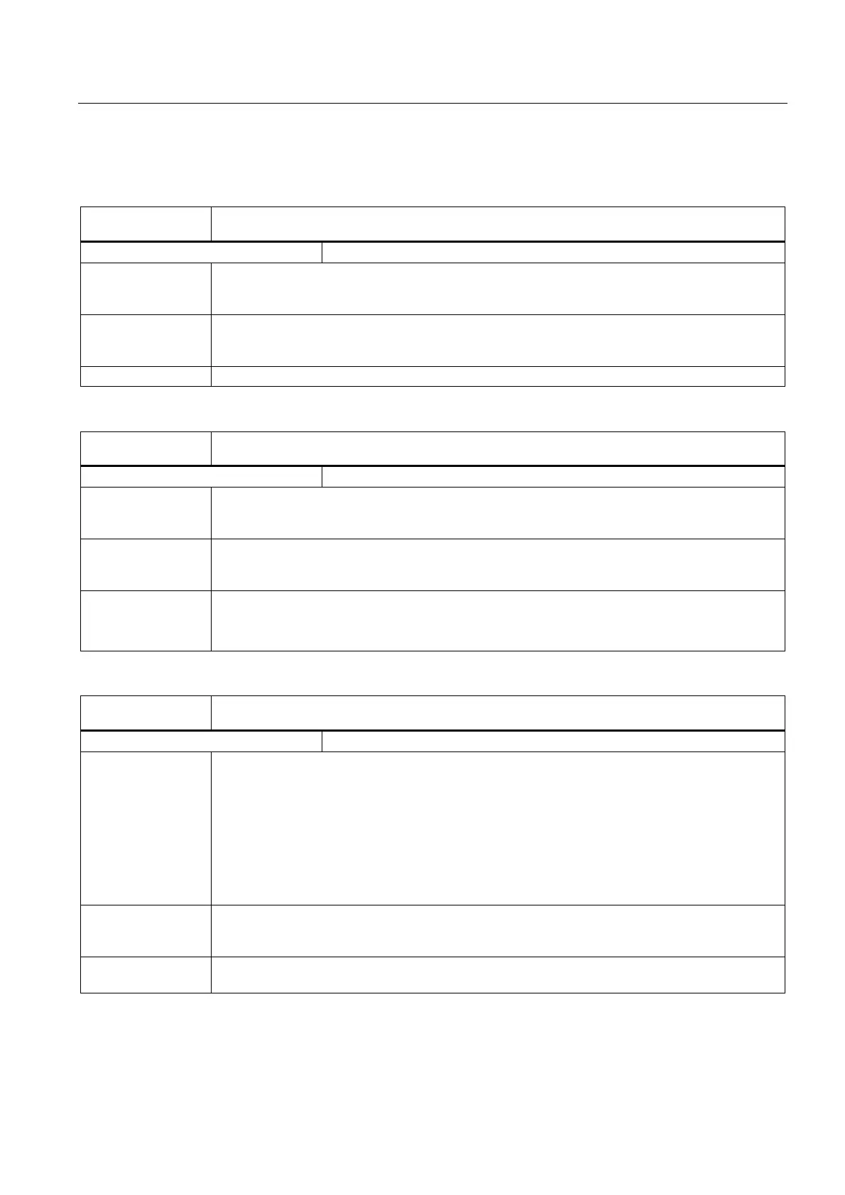
DB31, ...
DBX2.3
Clamping in progress
Edge evaluation: no Signal(s) updated: cyclic
Signal state 1 or
edge change
0 → 1
Clamping in progress.
The clamping monitoring function is activated.
Signal state 0 or
edge change
1 → 0
Clamping completed.
The clamping monitoring function is replaced by the standstill (zero speed) monitoring.
Corresponding to .... MD36050 $MA_CLAMP_POS_TOL (Clamping tolerance)
DB31, ...
DBX3.6
Velocity/spindle speed limitation
Edge evaluation: no Signal(s) updated: cyclic
Signal state 1 or
edge change
0 → 1
The NCK limits the velocity/spindle speed to the limit value set in the machine data:
MD35160 $MA_SPIND_EXTERN_VELO_LIMIT
Signal state 0 or
edge change
1 → 0
No limitation active.
Corresponding to .... MD35100 $MA_SPIND_VELO_LIMIT (max. spindle speed)
SD43220 $SA_SPIND_MAX_VELO_G26 (prog. spindle speed limiting G26)
MD43230 $SA_SPIND_MAX_VELO_LIMIT (prog. spindle speed limiting G96/G961)
DB31, ...
DBX12.0 - DBX12.1
Hardware limit switches plus and minus
Edge evaluation: no Signal(s) updated: cyclic
Signal state 1 or
edge change
0 → 1
A switch can be mounted at each end of the travel range of a machine axis which will cause a
signal "hardware limit switch plus or minus" to be signaled to the NC via the PLC if it is actuated.
If the signal is recognized as set, alarm 021614 "hardware limit switch + or -" is output and the axis
is decelerated immediately.
The braking/deceleration type is defined using the machine data:
MD36600 $MA_BRAKE_MODE_CHOICE (braking behavior at the hardware limit switch)
If the controller enable is withdrawn at the same time as the "hardware limit switch" signal, then the
axis responds as described in Chapter A2 ("various interface signals").
Signal state 0 or
edge change
1 → 0
Normal condition - a hardware limit switch has not been actuated.
Corresponding to .... MD36600 $MA_BRAKE_MODE_CHOICE (deceleration behavior when the hardware limit switch
responds)
 Loading...


