Detailed description
2.12 Block descriptions
Basic logic functions: PLC basic program solution line (P3 sl)
242 Function Manual, 11/2006, 6FC5397-0BP10-2BA0
Description of formal parameters
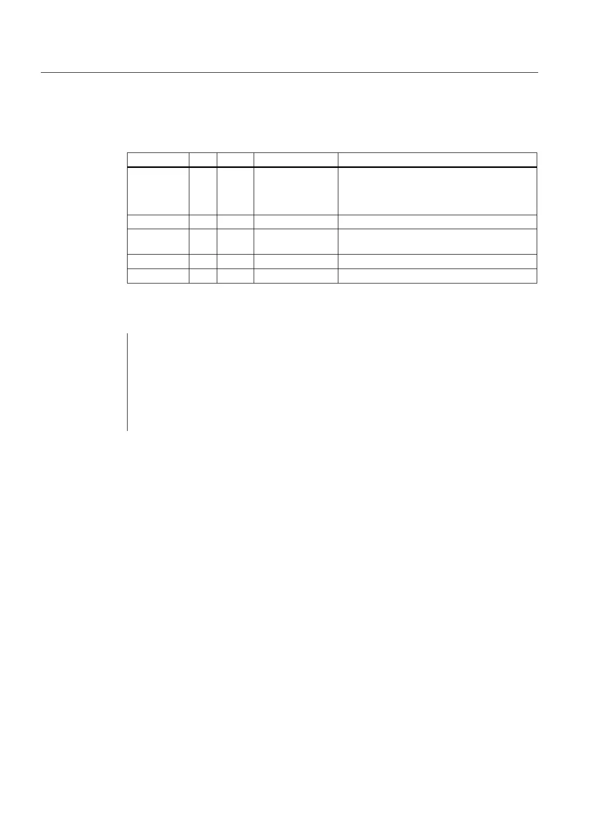
The table below shows all formal parameters of the "MCP_IFT" function:
Signal Type Type Range of values Remark
BAGNo I BYTE 0 - b#16#0A and
b#16#10 -b#16#1A
No. of mode group to which the mode signals
are transferred.
BAGNo >= b#16#10 means access to the
second machine control panel.
ChanNo I BYTE 0 - B#16#0A Channel no. for the channel signals
SpindleIFNo I BYTE 0 - 31
(B#16#1F)
Number of the axis interface declared as a
spindle
FeedHold A BOOL Feed stop from MCP, modal
SpindleHold A BOOL Spindle stop from MCP, modal
Call example
CALL FC 25 (
//Machine control panel T variants
//signals to interface
BAGNo := B#16#1, //Mode group no. 1
ChanNo := B#16#1, //Channel no. 1
SpindleIFNo := B#16#4, //Spindle interface number = 4
FeedHold := m22.0, //Feed stop signal modal
SpindleHold := db2.dbx151.0); //Spindle stop modal in message data block
With these parameter settings, the signals are sent to the 1st mode group, the 1st channel
and all axes. In addition, the spindle override is transferred to the 4th axis/spindle interface.
The feed hold signal is passed to bit memory 22.0 and the spindle stop signal to data block
DB2, data bit 151.0.
2.12.27 FC 26: HPU_MCP transmission of HT8 signals to interface
Description of functions
With FC HPU_MCP (machine control panel signals of the handheld programming device
HT8), the following are transferred from the machine control panel (MCP) to the
corresponding signals of the NCK/PLC interface:
• Mode groups
• WCS/MCS switchover
• Traversing keys
• Override
In the basic program (FC 2), handwheel selections, modes and other operating signals
continue to be transferred from the operator panel front or HMI to the NCK/PLC interface so
that the modes support selection from the MCP or HMI.
 Loading...


