Brief description
1.2 Overview of auxiliary functions
Basic logic functions: Auxiliary Function Output to PLC (H2)
Function Manual, 11/2006, 6FC5397-0BP10-2BA0
7
Definition of an auxiliary function
An auxiliary function is defined by the following parameters:
• Type, address extension, and value
The 3 parameters are output to the NC/PLC interface.
• Output behavior
The auxiliary-function-specific output behavior defines for how long an auxiliary function
is output to the NC/PLC interface and when it is output relative to the traverse movement
programmed in the same parts program block.
• Group assignment
An auxiliary function can be assigned to a particular auxiliary function group. The output
behavior can be defined separately for each auxiliary function group. This becomes
active if no auxiliary-function-specific output behavior has been defined. Group
membership also affects output of an auxiliary function after block search.
For more detailed information on auxiliary function output to the NC/PLC interface, see:
References:
/FB1/ Function Manual, Basic Functions, Basic PLC Program (P3)
1.2 Overview of auxiliary functions
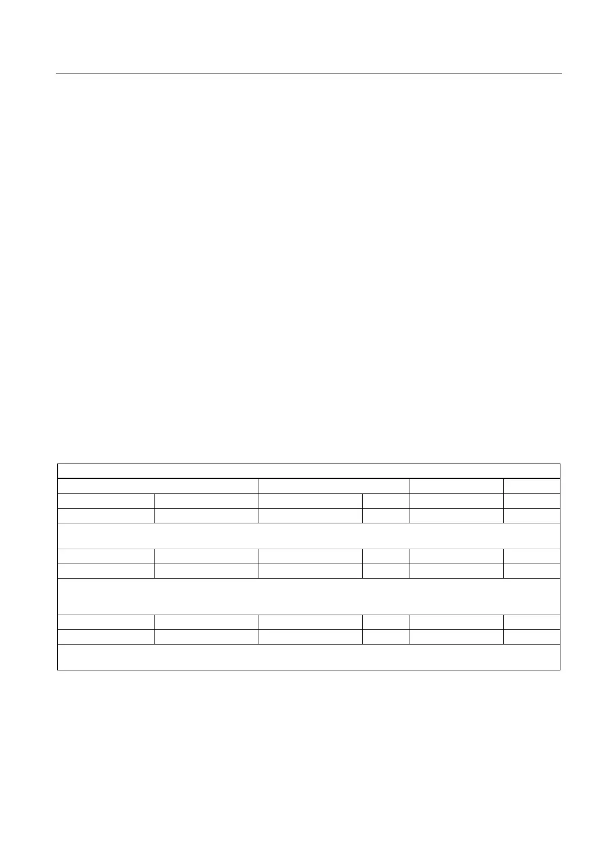
M functions
M (special function)
Address extension Value
Value range Meaning Value range Type Meaning Number
8)
0 (implicit) - - - up to 8 digits INT Function 5
Remarks:
- - -
Value range Meaning Value range Type Meaning Number
8)
1 - 12 Spindle number 1 – 99 INT Function 5
Remarks:
Example: "Spindle stop" for 2nd spindle of the channel: M2=5.
The master spindle of the channel is addressed if no an address extension is specified.
Value range Meaning Value range Type Meaning Number
8)
0 - 99 Any 2147483647 INT Function 5
Remarks:
User-specific M function
 Loading...


