Detailed description
2.7 Structure and functions of the basic program
Basic logic functions: PLC basic program solution line (P3 sl)
58 Function Manual, 11/2006, 6FC5397-0BP10-2BA0
2.7.8 Symbolic programming of user program with interface DB
General
Note
The basic program library on the CD supplied with the Toolbox for the 840D contains files
NST_UDTB.AWL and TM_UDTB.AWL.
The compiled UDT blocks from these two files are stored in the CPU program of the basic
program.
A UDT is a data type defined by the user that can, for example, be assigned to a data block
generated in the CPU.
Symbolic names of virtually all the interface signals are defined in these UDT blocks.
The UDT numbers 2, 10, 11, 19, 21, 31, 71, 72, 73 are used.
The assignments have been made as follows:
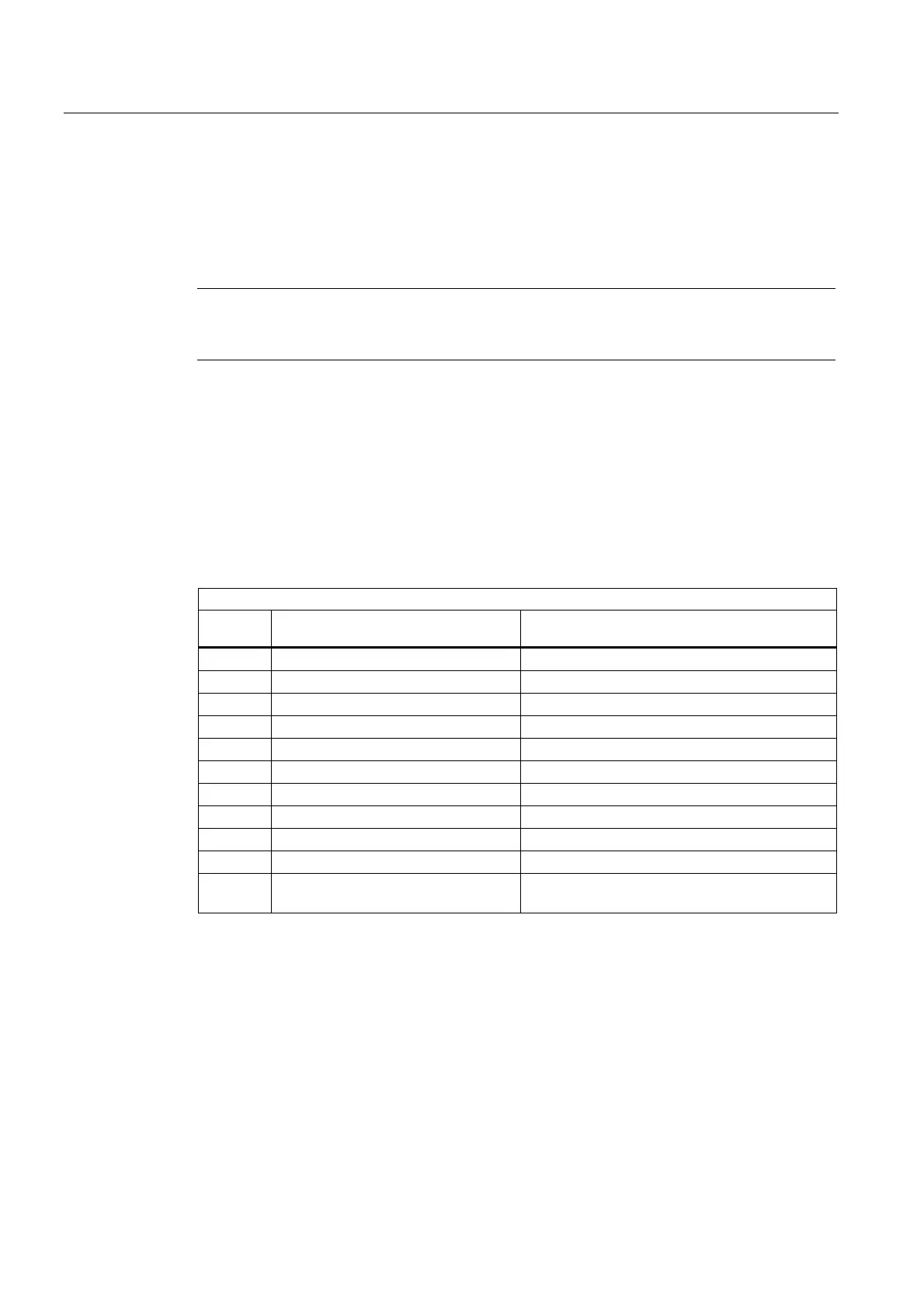
UDT assignments
UDT
number
Assignment to interface DB Significance
UDT 2 DB 2 Interrupts/Messages
UDT 10 DB 10 NCK signals
UDT 11 DB 11 Mode group signals
UDT 19 DB 19 HMI signals
UDT 21 DB 21 to DB 30 Channel signal
UDT 31 DB 31 to DB 61 Axis/spindle signals
UDT 71 DB71 Tool management: Load/unload locations
UDT 72 DB 72 Tool management: Change in spindle
UDT 73 DB 73 Tool management: Change in revolver
UDT77 DB 77 MCP and HHU signals with standard SDB 210
UDT1002 DB 2 extended alarms / messages (FB 1-Parameter
"ExtendAlMsg:=TRUE"
To symbolically program the interface signals, the interface data blocks must first be
symbolically assigned using the symbol editor.
For example, symbol "AxisX" is assigned to operand DB31 with data type UDT 31 in the
symbol file.
After this input, the STEP 7 program can be programmed in symbols for this interface.
 Loading...


