Detailed description
2.9 Program control
Basic logic functions: Mode group, channel, program operation, reset response (K1)
156 Function Manual, 11/2006, 6FC5397-0BP10-2BA0
2.9.6 Structure for a DIN block
Structure of display block for a DIN block
Basic structure of display block for a DIN block
• Block number/label
• G function of first G group
(only when altered as compared to the last machine function block).
• Axis positions
(sequence according to MD20070 $MC_AXCONF_MACHAX_USED).
• Other modal G functions
(only when altered as compared to the last machine function block).
• Other addresses as programmed.
The display block for the basic block display is directly derived from the programmed part
program blocks according to the following rules:
• Macros are expanded.
• Skip identifiers and comments are omitted.
• Block number and labels are transferred from the original block, but omitted if DISPLOF is
active.
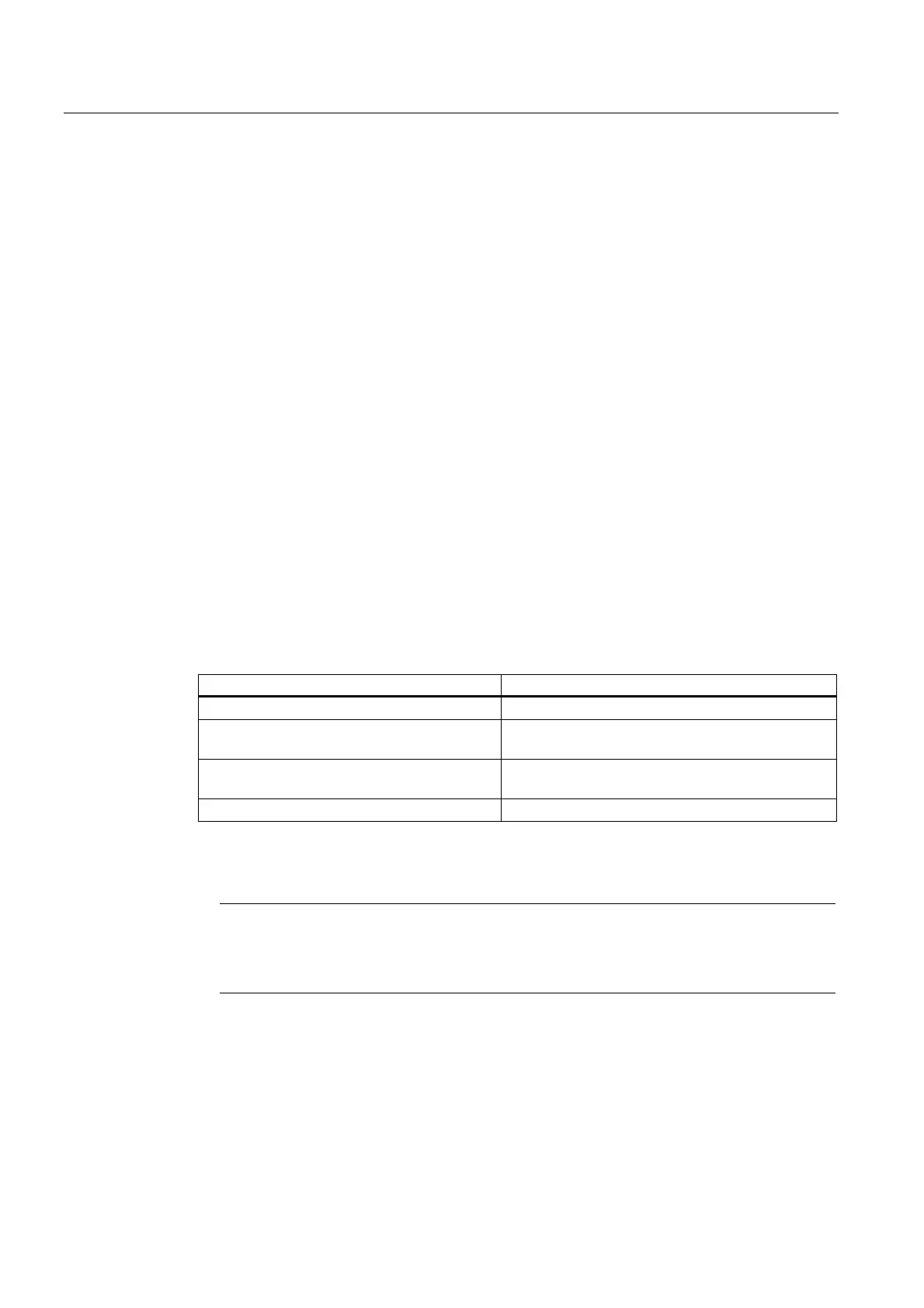
• The number of decimal places is defined in display machine data MD 9004, MD 9010 and
MD 9011 via the HMI.
HMI display machine data Access in NCK machine data
MD9004 $MM_DISPLAY_RESOLUTION MD17200 $MN_GMMC_INFO_NO_UNIT[0]
MD9011
$MM_DISPLAY_RESOLUTION_INCH
MD17200 $MN_GMMC_INFO_NO_UNIT[1]
MD9010
$MM_SPIND_DISPLAY_RESOLUTION
MD17200 $MN_GMMC_INFO_NO_UNIT[2]
MD9424 $MM_MA_COORDINATE_SYSTEM MD17200 $MN_GMMC_INFO_NO_UNIT[3]
• Programmed axis positions are represented as absolute positions in the coordinate
system (WKS / ENS) specified in MD9424 $MM_MA_COORDINATE_SYSTEM.
Note
The modulo correction is omitted for modulo axes, which means that positions outside the
modulo range can be displayed. It also means that the basic block display differs from the
position display in which values are always moduloconverted.
 Loading...


