Detailed Description
2.4 Tool radius compensation 2D (TRC)
Basic logic functions: Tool Offset (W1)
52 Function Manual, 11/2006, 6FC5397-0BP10-2BA0
Why TRC?
The contour (geometry) of the workpiece programmed in the part program should be
independent of the tools used in production. This makes it necessary to draw the values for
the tool length and tool radius from a current offset memory. Tool radius compensation can
be used to calculate the equidistant path to the programmed contour from the current tool
radius.
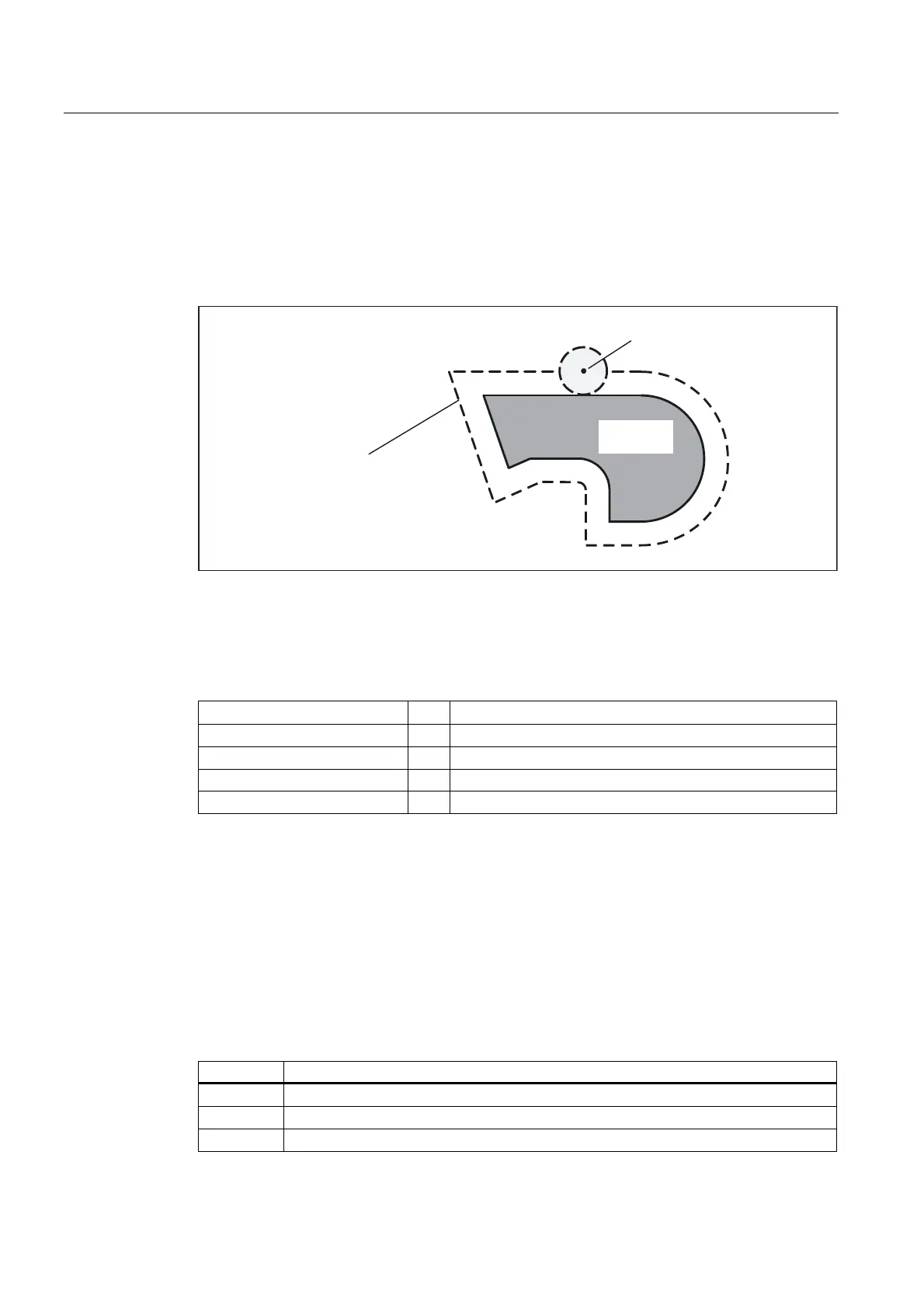
7RRO
3DWKRIWKHWRROFHQWHUSRLQW
DWHTXDOGLVWDQFHWRWKH
FRQWRXUHTXLGLVWDQWSDWK
:RUNSLHFH
FRQWRXU
Figure 2-15 Workpiece contour (geometry) with equidistant path
TRC on the plane
TRC is active on the current plane (G17 to G19) for the following types of interpolation:
• Linear interpolation
...
G0,G1
• Circular interpolation
...
G2, G3, CIP
• Helical interpolation
...
G2,G3
• Spline interpolation
...
ASPLINE, BSPLINE, CSPLINE
• Polynomial interpolation
...
POLY
2.4.2 Selecting the TRC (G41/G42)
Direction of compensation
TRC calculates a path, which is equidistant to the programmed contour. Compensation can
be performed on the left- or righthand side of the programmed contour in the direction of
motion.
Command Significance
G41
TRC on the lefthand side of the contour in the direction of motion
G42
TRC on the righthand side of the contour in the direction of motion
G40
Deselection of TRC
 Loading...


