Detailed description
2.7 Structure and functions of the basic program
Basic logic functions: PLC Basic program powerline (P3 pl)
Function Manual, 11/2006, 6FC5397-0BP10-2BA0
71
Configuring
Essentially, there are two communication mechanisms for transferring data between the
MCP/HHU and PLC. These mechanisms are determined by the connection of the MCP and
HHU. With the first mechanism, data are transported via the COM module (840D/810D). The
parameter setting is thereby done completely via the MSTT/BHG parameter in the FB1.
In the second case, data are transferred via the PLC operating system (FM-NC) by means of
the evaluation of SDB210 (global data) or via the Profibus configuration. The mechanism is
parameterized via STEP7 -> Global Data or in HW Config. To allow the basic program to
access these data and implement MCP/HHU failure monitoring, the addresses set via
SDB210 (global data) must be declared in the FB1 parameters in the basic program.
An overview of the various interfacing options as a function of the NC type used is given
below. In each case, the parameter set of FB1 and the valid status information relevant for
the respective data transmission method are specified.
If an error is detected due to a timeout monitor, a corresponding entry is made in the
diagnostic buffer of the PLC CPU (errors 400260 to 400262). In this case, the input signals
from the MCP or from the handheld unit (MCP1In/MCP2In or BHGIn) are initialized with 0. If
it is possible to resynchronize the PLC and MCP/HHU, communication is resumed
automatically and the error message reset by the BP.
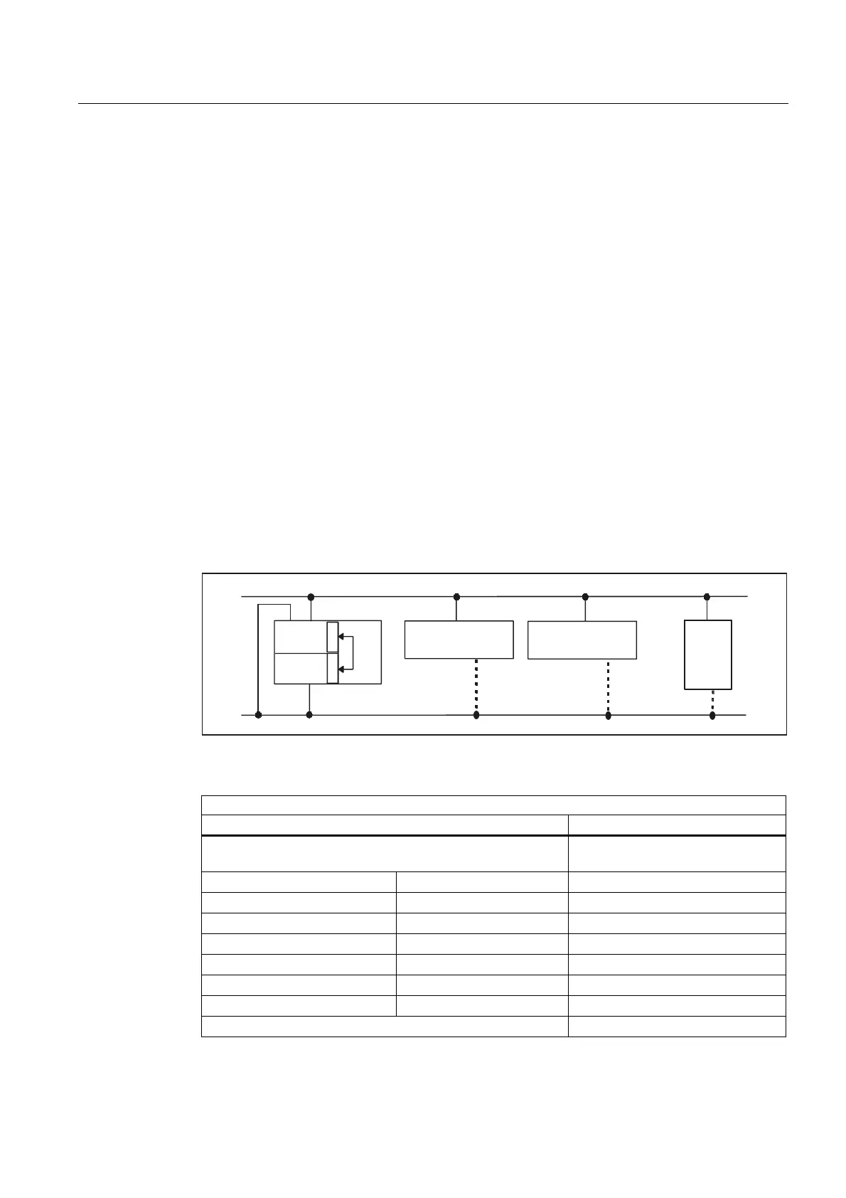
840D: OPI/MPI connection
Communication starts from the PLC BP via the NCK and COM mode, i.e., even a link via the
MPI does not require an SDB210. Parameter settings are made via the relevant parameters
in FB1.
03,
++8
1&.
5
3
'
23,
0&3
0&3
5
3
'
LQW
3/&
&200
PRGXOH
Figure 2-15 840D: OPI/MPI connection
Relevant parameters (FB1)
MCP HHU
MCPNum=1 or 2 (number of MCPs) BHG=2
(transfer via COM module)
MCP1In MCP2In BHGIn
MCP1Out MCP2Out BHGOut
MCP1StatSend MCP2StatSend BHGStatSend
MCP1StatRec MCP2StatRec BHGStatRec
MCP1BusAdr MCP2BusAdr BHGInLen
MCP1Timeout MCP2Timeout BHGOutLen
MCP1Cycl MCP2Cycl BHGTimeout
MCPMPI = FALSE (OPI), TRUE (MPI) BHGCycl
 Loading...


