Detailed description
2.12 Block descriptions
Basic logic functions: PLC Basic program powerline (P3 pl)
232 Function Manual, 11/2006, 6FC5397-0BP10-2BA0
For FC 19, the maximum possible number of axis selections can also be restricted.
This upper limit is set for the
1. Machine Control Panel in DB10, ... DBW30 (symbolic Name: MCP1MaxAxis) or for the
2. Machine Control Panel in DB10, ... DBW54 (symbolic Name: MCP2MaxAxis) for the
respective MSTT.
The default setting is 0, corresponding to the maximum number of configured axes. The axis
numbers and the limit can also be adapted dynamically. Afterwards, a new axis must be
selected on FC 19. Axis numbers may not be switched over while the axes are traversing the
relevant direction keys.
The compatibility mode is preset with axis numbers 1 to 9 for both MCPs and the restriction
for the configured number of axes.
Declaration of the function
FUNCTION FC 19: VOID
// NAME:
MCP_IFM
VAR_INPUT
BAGNo : BYTE ;
ChanNo: BYTE ;
SpindleIFNo: BYTE ;
END_VAR
VAR_OUTPUT
FeedHold : BOOL ;
SpindleHold : BOOL ;
END_VAR
BEGIN
END_FUNCTION
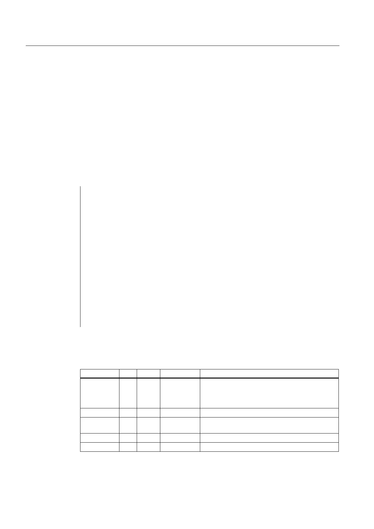
Description of the formal parameters
The table below shows all formal parameters of the "MCP_IFM" function:
Signal I/O Type Value range Remark
BAGNo I BYTE 0 - b#16# and
b#16#10 -
b#16#1A
No. of mode group to which the mode signals are
transferred.
BAGNo >= b#16#10 means access to the
second machine control panel.
ChanNo I BYTE 0 - B#16#0A Channel no. for the channel signals
SpindleIFNo I BYTE 0 - 31
(B#16#1F)
Number of the axis interface declared as a spindle
FeedHold Q BOOL Feed stop from machine control panel, modal
SpindleHold Q BOOL Spindle stop from machine control panel, modal
 Loading...


