Detailed description
2.6 Interface structure
Basic logic functions: PLC basic program solution line (P3 sl)
44 Function Manual, 11/2006, 6FC5397-0BP10-2BA0
(WKHUQHWEXV
(QJLQHHULQJ
(WKHUQHWEXV
++8
7&8
0&3
3*
3/&
1&.
&3'VO
)%
):
0&3
VLJ
'35
&XVWRPL]HG
NH\VGLVSOD\V
+0,
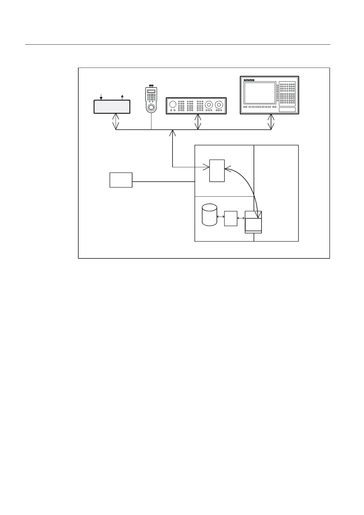
Figure 2-10 Connection of the machine control panel on 840D
Topology SINUMERIK 840Di
On the 840 Di, the machine control panel and handheld unit are connected to the PLC's MPI
(MultiPoint Interface) or Profibus. The PLC operating system copies the incoming signals
straight to the user interface (e.g., input image) at the cycle control point. As on the
SINUMERIK 840 D, transfer to the VDI interface is performed by the user program or by
standard blocks of the basic program (e.g. FC19).
Bus addresses
On Ethernet components, MAC and IP addresses or logic names are determining factors in
respect of communication. The control system's system programs convert logic names into
MAC or IP addresses. On the PLC, the numeric component of the logic name is used for
communication. This numeric part is assigned to FB1 parameter "MCPxBusAdr" by the user.
The logical name of an MCP or HHU always begins with "DIP". This is followed by a number
corresponding to the switch position of the MCP component (e.g. DIP 192, DIP 17).
 Loading...


