Detailed description
2.7 Structure and functions of the basic program
Basic logic functions: PLC basic program solution line (P3 sl)
Function Manual, 11/2006, 6FC5397-0BP10-2BA0
69
Configuration
Essentially, there are various communication mechanisms for transferring data between the
MCP/HHU and PLC. These mechanisms are characterized by the bus connection of the
MCP and HHU. In one case (Ethernet), data is transported via the "CP840D sl".
The mechanism is parameterized completely via the MCP/HHU parameters in FB1.
In the other case the transmission is done through the PLC-operating system through the
Profibus configuration
The parameterization is done via STEP 7 in HW-Config. To enable the basic program to
access these data and failure monitoring of MCP/HHU, the addresses set in FB 1-
parameters must be made available to the basic program.
An overview of the various coupling mechanisms appears below. Mixed operation can also
be configured.
If an error is detected due to a timeout monitor, an entry is made in the alarm buffer of the
PLC CPU (interrupts 400260 to 400262). In this case, the input signals from the MCP or from
the handheld unit (MCP1In/MCP2In or BHGIn) are reset to 0. If it is possible to
resynchronize the PLC and MCP/HHU, communication is resumed automatically and the
error message reset by the GP.
Note
In the following tables, "(n.r.)" indicates "not relevant".
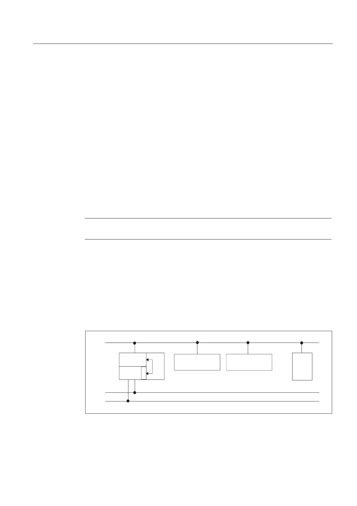
840D: Ethernet connection
Without further configuration settings being made, communication takes place directly from
the PLC GP via the CP 840D sl. The FB 1 parameters listed below are used for
parameterization.
The numeric part of the logical name of the component must be entered in "MCP1 BusAdr",
"MCP2 BusAdr" or "BHGRecGDNo" (corresponds to the bus address of node). The logical
name is defined via switches on the MCP or terminal box.
03,'3
'3
++8
1&
(WKHUQHW
0&3
0&3
'
3
5
&3
'VO
LQW
3/&
Figure 2-16 840D sl: Ethernet connection
 Loading...


