Detailed description
2.12 Block descriptions
Basic logic functions: PLC basic program solution line (P3 sl)
226 Function Manual, 11/2006, 6FC5397-0BP10-2BA0
Declaration of the function
STL representation
VAR_INPUT
Enable : BOOL ;
Funct: BYTE ;
S7Var : ANY ;
IVar1 : INT ;
IVar2 : INT ;
END_VAR
VAR_OUTPUT
Error : BOOL ;
ErrCode : INT ;
END_VAR
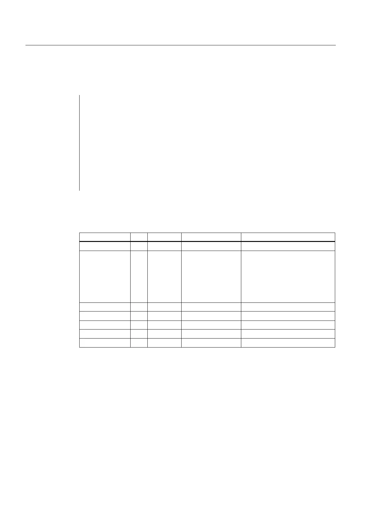
Explanation of formal parameters
The table below shows all formal parameters of the "Transfer" function.
Signal Type Type Value range Remark
Enable I BOOL 1 = FC 21 active
Funct I BYTE 1.. 7 1: Synchronized actions to channel
2: Synchronized actions from
channel
3: Read data
4: Write data
5: Control signals to channel
6, 7: Control signals to axis
S7Var I ANY S7 data storage area Depends on "Funct"
IVAR1 I INT 0.. Depends on "Funct"
IVAR2 I INT 1.. Depends on "Funct"
Error A BOOL
ErrCode A INT Depends on "Funct"
Functions
1: Signals for synchronized actions to channel:
2: Signals for synchronized actions from channel:
Synchronized actions can be disabled or enabled by the PLC.
The data area is stored on the user interface in DB21 to DB30.DBB 300..307 (to channel)
and DBB 308..315 (from channel). The parameter "S7Var" is not evaluated for this function,
but must be assigned an actual parameter (see call example). The data are transferred
to/from the NC as soon as FC 21 is processed.
The following signals are relevant:
 Loading...


