Detailed description
2.4 Referencing with incremental measurement systems
Basic logic functions: Reference Point Approach (R1)
14 Function Manual, 11/2006, 6FC5397-0BP10-2BA0
MD34020 $MA_REFP_VELO_SEARCH_CAM (Reference point approach velocity)
The PLC user program communicates to the NC that the reference cam has been reached
via the following interface signal:
DB31, ... DBX12.7 (reference point approach deceleration)
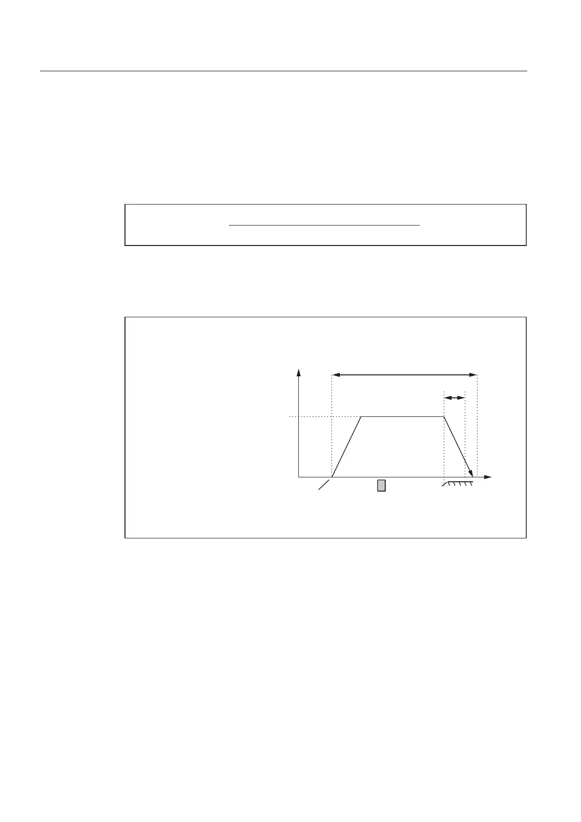
As a result the NC decelerates to zero speed. The following distance s
min
is still minimally
back tracked:
60,1
0'0$B5()3B9(/2B6($5&+B0$5.(5
0'0$B0$;B$;B$&&(/
This minimum distance is required to ensure that the machine axis exits the reference cam in
Phase 2 at the parameterized reference point creep velocity.
Phase 1 is now complete. Reference point approach is continued with Phase 2.
5HIHUHQFHSRLQWDSSURDFKYHORFLW\
6WDUWLQJSRVLWLRQ
RID[LV
0LQLPXPGLVWDQFH
5HIHUHQFHSRLQWFDP
9HORFLW\
0D[LPXPGLVWDQFHWRUHIHUHQFHFDP
=HURPDUN
'LVWDQFH
0'0$B5()3B0$;B&$0B',67
0'0$B5()3B9(/2B6($5&+B&$0
Figure 2-3 Minimum distance for deceleration
Case 2: The machine axis is positioned on the reference cam
The machine axis remains at its starting position.
Phase 1 is now complete. Reference point approach is continued with Phase 2.
Case 3: The machine axis has no reference cam
Machine axes without reference point cams remain at their starting position.
These include, for example:
• Machine axes that only have one zero mark along their entire traversing range
• Rotary axes that only have one zero mark per revolution
 Loading...


