Detailed description
2.4 Referencing with incremental measurement systems
Basic logic functions: Reference Point Approach (R1)
Function Manual, 11/2006, 6FC5397-0BP10-2BA0
17
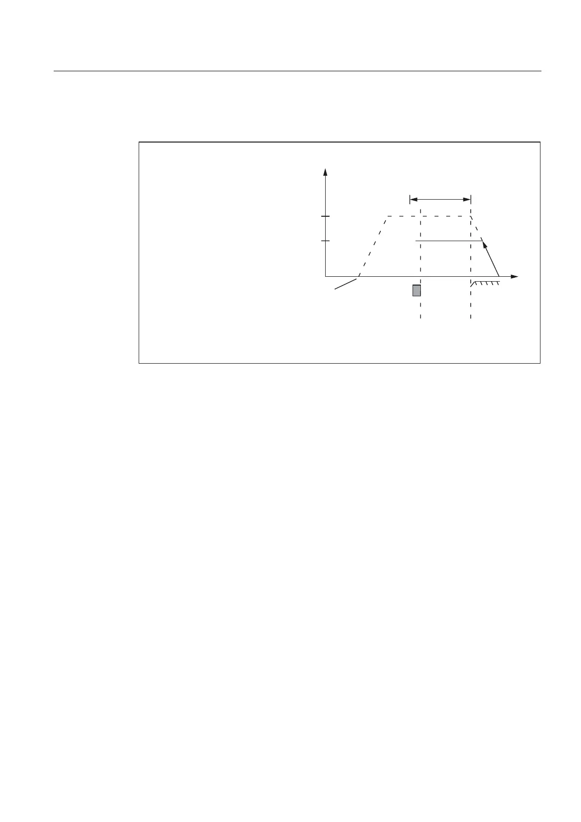
As soon as the encoder zero mark is detected, Phase 2 comes to an end. The machine axis
continues at constant velocity and reference point approach is continued with phase 3.
5HIHUHQFHSRLQWDSSURDFKYHORFLW\
6WDUWLQJSRVLWLRQ
RID[LV
5HIHUHQFH
SRLQWFDP
'HFHOHUDWLRQ
5HIHUHQFHSRLQW
DSSURDFK
9HORFLW\
5HIHUHQFHSRLQWFUHHSYHORFLW\
=HUR
0DUN
0D['LVWDQFHWRUHIHUHQFHPDUN
'LVWDQFH
0'0$B5()3B0$;B0$5.(5B',67
0'0$B5()3B9(/2B6($5&+B0$5.(5
0'0$B5()3B9(/2B6($5&+B&$0
Figure 2-5 Synchronization with falling reference cam signal edge
Case 2: Synchronization with rising reference cam edge
During synchronization with rising reference cam signal edge, the machine axis accelerates
to the parameterized reference point approach velocity against the parameterized reference
point approach direction (traversing direction of the phase 1):
MD34020 $MA_REFP_VELO_SEARCH_CAM (Reference point approach velocity)
MD34010 $MA_REFP_CAM_DIR_IS_MINUS (Reference point approach in minus direction)
After the reference cam is exited (DB31, ... DBX12.7 = 0), the machine axis is decelerated to
stillstand.
The machine axis then travels back to the reference cam at the parameterized reference
point creep velocity:
MD34040 $MA_REFP_VELO_SEARCH_MARKER (reference point creep velocity)
After the reference cam is reached (DB31, ... DBX12.7 = 1), the next encoder zero mark is
awaited.
As soon as the encoder zero mark is detected, Phase 2 comes to an end. The machine axis
continues at constant velocity and reference point approach is continued with phase 3.
 Loading...


