Detailed description
2.4 Referencing with incremental measurement systems
Basic logic functions: Reference Point Approach (R1)
Function Manual, 11/2006, 6FC5397-0BP10-2BA0
19
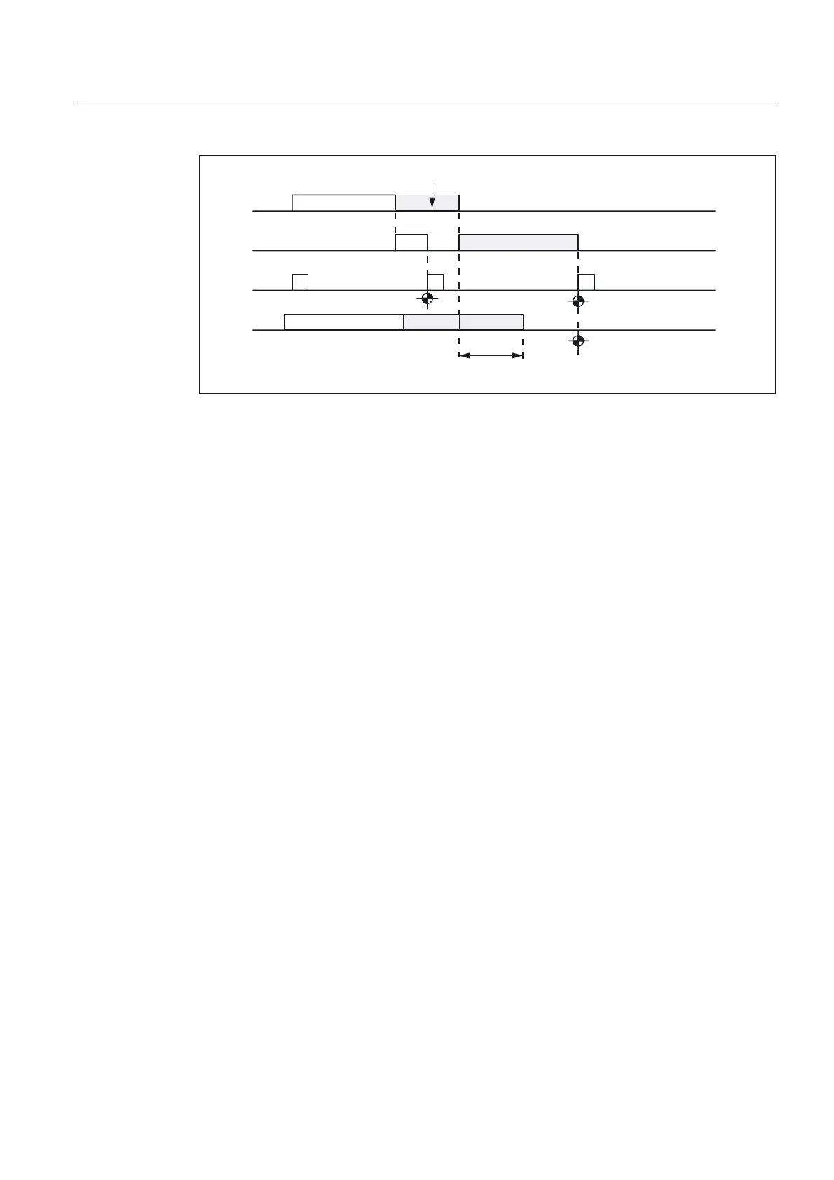
7KHUPDOH[SDQVLRQ
&DPVLJQDO
=HURPDUNVHDUFK
=HURPDUN
&DPVLJQDOZLWK
RIIVHW
0'0$B5()3B&$0B6+,)7
Figure 2-7 Electronic reference cam offset
Reference cam adjustment
Encoder with equidistant zero marks
Always ensure that the reference cam of encoders that supply zero marks at equidistances
is accurately adjusted so that the correct zero mark is always detected during reference point
approach.
Dynamic response
The following factors influence the dynamic response from the arrival of the reference cam to
the machine up to the detection of reference cam signals transferred from the PLC user
program to the NC:
• Switching accuracy of the reference cam switch
• Delay of the reference cam switch (NC contact)
• Delay at the PLC input
• PLC cycle time
• Cycle time for updating the VDI interface
• Interpolation cycle
• Position control cycle
Setting notes
• reference cam
Aligning the signal edge of the reference cam directly between two zero marks has
proven to be the most practical method.
• Electronic reference cam offset
Information needed for parameterizing the electronic reference cam offset is to be found
in the read-only machine data:
MD34093 $MA_REFP_CAM_MARKER_DIST (distance between reference cam/reference
mark)
 Loading...


