Detailed description
2.5 Referencing with distancecoded reference marks
Basic logic functions: Reference Point Approach (R1)
Function Manual, 11/2006, 6FC5397-0BP10-2BA0
27
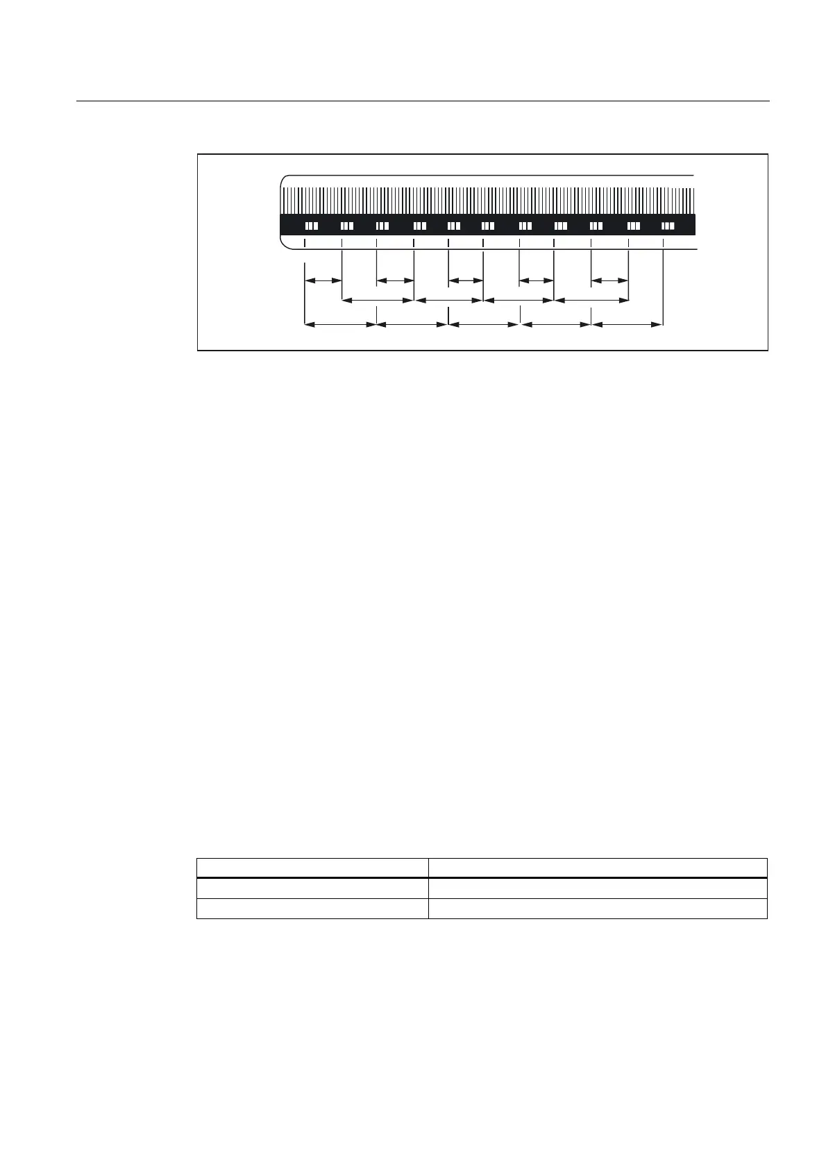
5HIHUHQFHPDUN
Figure 2-11 DIADUR graduated glass scale with distance-coded reference marks
(dimensions in mm for 20 mm scale division)
Rotary measuring system
For rotary measuring systems, the same applies as for linear measuring systems (see
above).
Determining the absolute offset
The following procedure is recommended for the determination of the absolute offset
between the machine zero point and the position of the first reference mark of a machine
axis:
1. Enter the value zero for the absolute offset:
MD34090 $MA_REFP_MOVE_DIST_CORR = 0
2. Perform reference point approach.
Note:Reference point approach should be performed at a point in the machine where the
exact position of the machine axis relative to machine zero can be determined easily with
a laser interferometer, for example.
3. Determine the actual position of the machine axis via the operator interface screen.
4. Measure the current position of the machine axis with reference to the machine zero
point.
5. Calculate absolute offset and enter in MD34090.
The absolute offset is calculated with respect to the machine coordinate system and
depending on the orientation of the measuring system (equidirectional or inverse) as:
Orientation of the measuring system Absolute offset
equidirectional Measured position + displayed actual position
Opposite direction Measured position - displayed actual position
 Loading...


