Detailed Description
2.1 Spindle modes
Basic logic functions: Spindles (S1)
8 Function Manual, 11/2006, 6FC5397-0BP10-2BA0
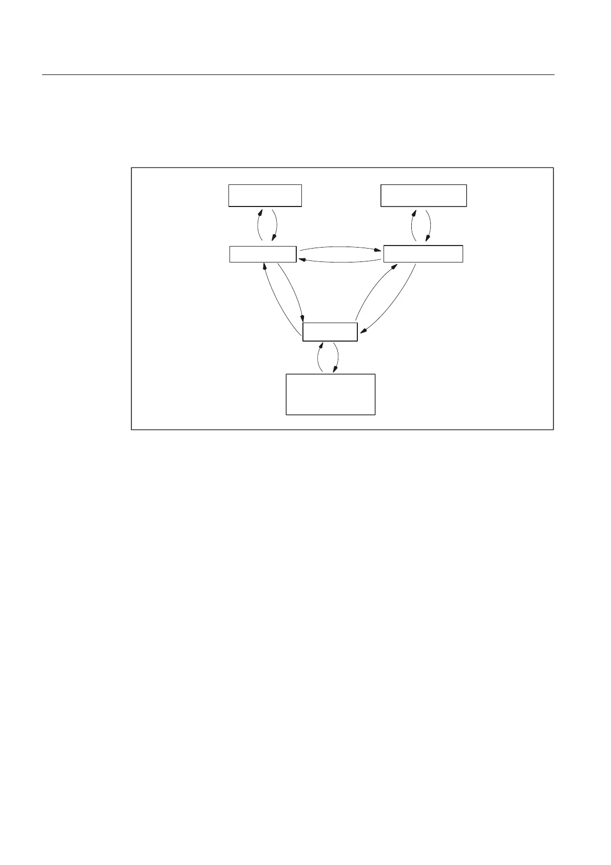
Switching between spindle modes
Interface signals or programming commands can be used to switch between the spindle
modes and axis operation:
63260
632606326$
63&2)
&28321
6326$
0
000
63&2)
0
0
000
*
*
&2832)
2VFLOODWLRQPRGH
2SHQORRS
FRQWUROPRGH
3RVLWLRQLQJPRGH
$[LVPRGH
$[LVQDPH
6\QFKURQRXV
PRGH
5LJLGWDSSLQJ
*HDU
FKDQJHG
&KDQJH
JHDU
Figure 2-1 Switching between spindle modes
• Open-loop control mode → Oscillation mode
The spindle changes to oscillation mode if a new gear step has been specified using
automatic gear step selection (M40) in conjunction with a new S value or by M41 to M45.
The spindle only changes to oscillation mode if the new gear step is not equal to the
current actual gear step.
• Oscillation mode → Open-loop control mode
When the new gear is engaged, IS:
DB31, ... DBX84.6 (Oscillation mode)
is reset and the spindle is switched
to open-loop control mode with IS:
DB31, ... DBX16.3 (Gear changed).
The last programmed spindle speed (S value) is reactivated.
• Open-loop control mode → Positioning mode
To stop the spindle from rotation (M3 or M4) with orientation or to reorient it from standstill
(M5), SPOS, M19 or SPOSA are used to switch to positioning mode.
• Positioning mode → Open-loop control mode
M3, M4 or M5 are used to change to open-loop control mode if the orientation of the
spindle is to be terminated. The last programmed spindle speed (S value) is reactivated.
 Loading...


