Detailed Description
2.1 Tool
Basic logic functions: Tool Offset (W1)
14 Function Manual, 11/2006, 6FC5397-0BP10-2BA0
Tools
The TO memory consists of tools numbered T1 to T32000.
Each tool can be set up via TOA files or individually, using the "New tool" soft key.
Compensation values not required must be assigned the value zero. (this is the default
setting when the offset memory is created): The individual values in the offset memory (tool
parameters) can be read and written from the program using system variables.
Note
The tools (T1 to T32000) do not have to be stored in ascending order or contiguously in the
tool compensation memory, and the first tool does not have to be assigned number T1.
Tool cutting edges
Each tool can have up to 9 cutting edges (D1 to D9). The first cutting edge (D1) is set up
automatically when a new tool is loaded in the tool compensation memory. Other cutting
edges (up to 8) are set up consecutively and contiguously using the "New cutting edge" soft
key. A different number of tool cutting edges can assigned to each tool in this way.
HWF
7
7
7
7
'
'
'
'
7
7
7
7
'
'
'
'
&KDQQHOHWF&KDQQHO
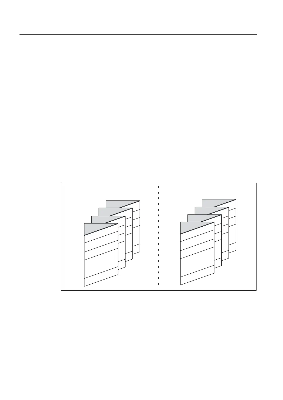
Figure 2-2 Example of a tool compensation memory structure for 2 channels
 Loading...


