Detailed Description
2.4 Tool radius compensation 2D (TRC)
Basic logic functions: Tool Offset (W1)
Function Manual, 11/2006, 6FC5397-0BP10-2BA0
65
$TC_DP1[1,1]=120
; Milling tool T1/D1
$TC_DP6 [1,1] = 7
; Tool with 7 mm radius
N10 G90 G0 X0 Y0 Z30 D1 T1
N20 X10
N30 G41 G147 DISCL=3 DISR=13 Z=0 F1000
N40 G1 X40 Y-10
N50 G1 X50
...
...
N30/N40 can be replaced by:
N30 G41 G147 DISCL=3 DISR=13 X40 Y-10 Z0 F1000
or:
N30 G41 G147 DISCL=3 DISR=13 F1000
N40 G1 X40 Y-10 Z0
Possible ways of programming the end point P
0
for retraction
The end position is always taken from the SAR block, no matter how many axes have been
programmed. We distinguish between the following situations:
1. No geometry axis is programmed in the SAR block.
In this case, the contour ends at point P
2
(or at point P
1
, if P
1
and P
2
coincide). The
position in the axes, which describe the machining plane, is determined by the retraction
contour (end point of the straight line or arc). The axis component perpendicular to this is
defined by DISCL. If, in this case, DISCL = 0, the movement takes place completely
within the plane.
2. Only the axis perpendicular to the machining plane is programmed in the SAR block.
In this case, the contour ends at point P
1
. The position of the two other axes is
determined in the same way as in 1.
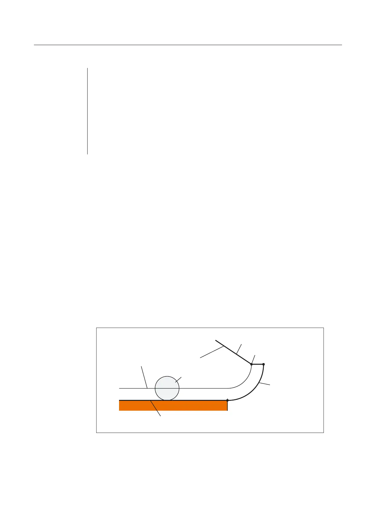
6$5EORFN
**
7RROFHQWHUSDWK
7RRO
&RQWRXUSUHFHGLQJEORFN
)ROORZLQJEORFNZLWKRXWRIIVHW
3
3
3
Retraction with SAR with simultaneous deactivation of TRC
 Loading...


