Detailed Description
2.9 Sum offsets and setup offsets
Basic logic functions: Tool Offset (W1)
Function Manual, 11/2006, 6FC5397-0BP10-2BA0
147
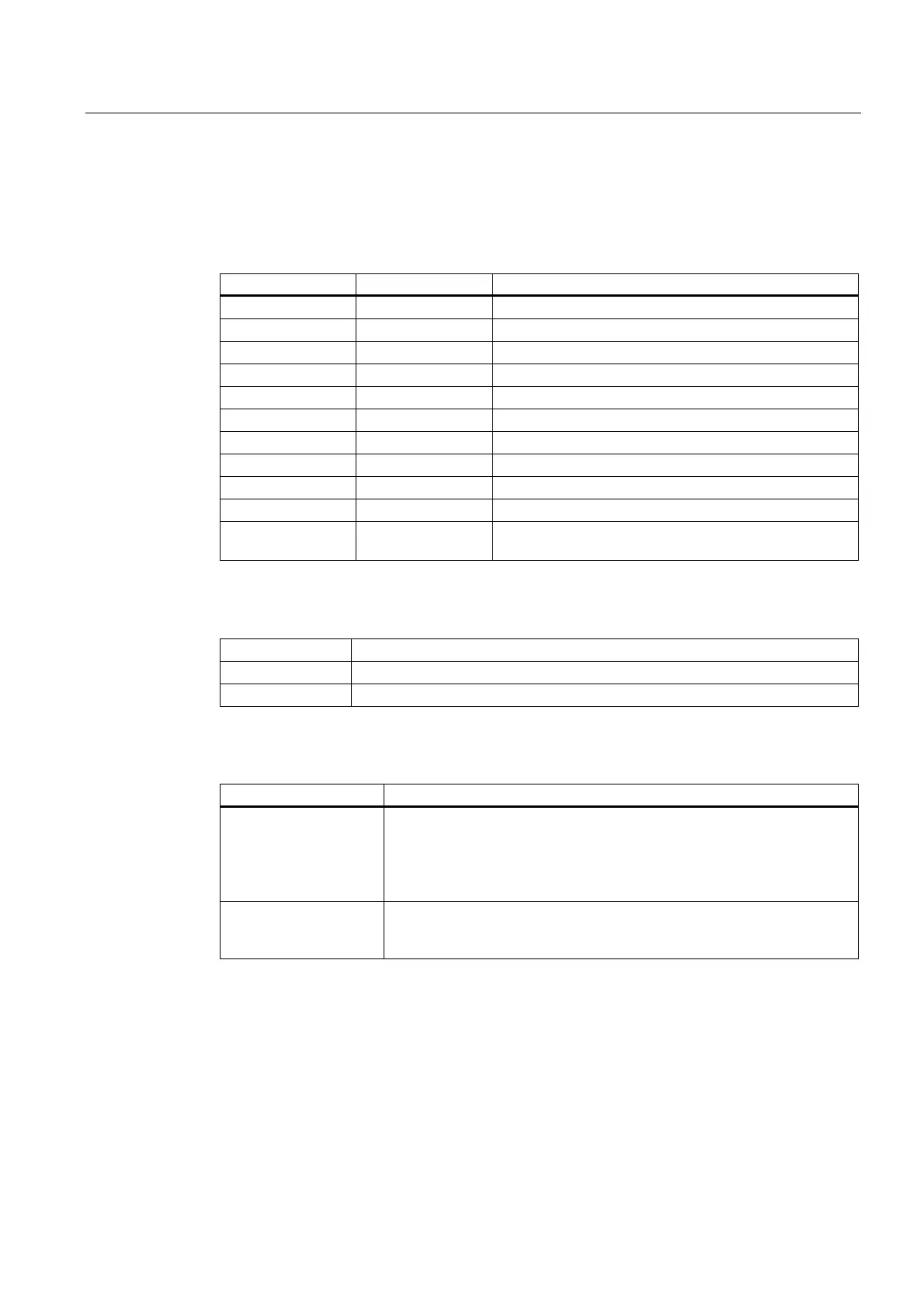
Parameters for geometry and wear
Tool geometry compensations are assigned to system variables $TC_DP3 to $TC_DP11.
System variables $TC_DP12 to $TC_DP20 allow you to name a wear for each of these
parameters.
Geometry Wear Length compensations
$TC_DP3 $TC_DP12 Length 1
$TC_DP4 $TC_DP13 Length 2
$TC_DP5 $TC_DP14 Length 3
Geometry Wear Radius compensation
$TC_DP6 $TC_DP15 Radius
$TC_DP7 $TC_DP16 Corner radius (tool type 700; slotting saw)
Geometry Wear Further compensations
$TC_DP8 $TC_DP17 Length 4 (tool type 700; slotting saw)
$TC_DP9 $TC_DP18 Length 5
$TC_DP10 $TC_DP19 Angle 1 (angle between face of tool and torus surface)
$TC_DP11 $TC_DP20 Angle 2 (angle between tool longitudinal axis and upper
end of torus surface)
Tool base dimension/adapter dimension
$TC_DP21 Adapter length 1
$TC_DP22 Adapter length 2
$TC_DP23 Adapter length 3
Technology
System variable Clearance angle
$TC_DP24
• The clearance angle is stored here for ManualTurn; tool type 5xx.
Same significance as in standard cycles for turning tools.
• The tip angle of the drill is stored here for ShopMill; tool type 2xx.
• Used in standard cycles for turning tools; tool type 5xx. This is the
angle at the secondary cutting edge for these tools.
$TC_DP25
• The value for the cutting rate is stored here for ManualTurn.
• A bitcoded value for various states of tool types 1xx and 2xx is stored
here for ShopMill.
 Loading...


