Detailed Description
2.1 Various interface signals and functions (A2)
Basic logic functions: NC/PLC interface signals (Z1)
30 Function Manual, 11/2006, 6FC5397-0BP10-2BA0
DB31, ...
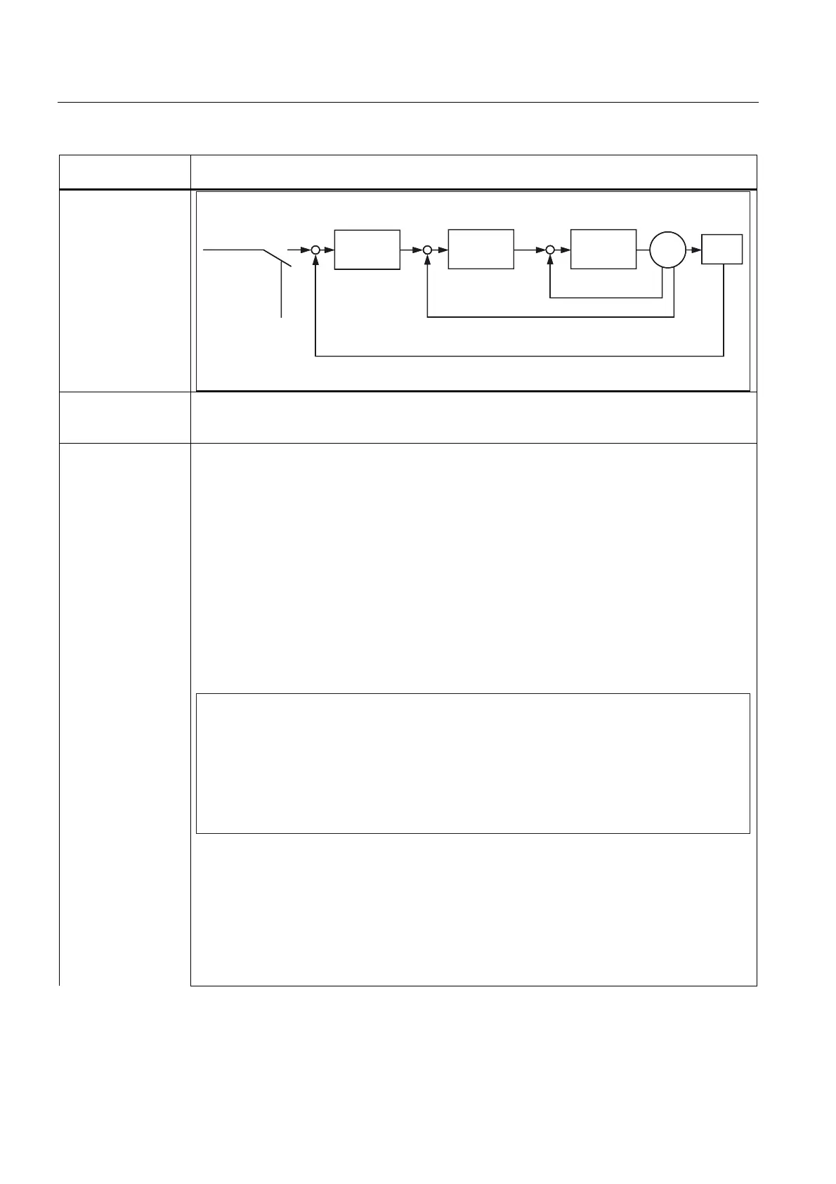
DBX1.3
Axis/spindle disable
BB
$FWXDOSRVLWLRQYDOXH
$[LVLQKLELW
DFWLYH
L
VHW
Q
DFW
L
DFW
(QFRGHU
0RWRU
&XUUHQW
FRQWUROOHU
6SHHG
FRQWUROOHU
3RVLWLRQ
FRQWUROOHU
3RVLWLRQ
VHWSRLQWIURP
WKHLQWHUSRODWRU
Application
example(s)
The interface signal "Axis disable" and "Spindle disable" is used when running-in and testing a new
NC part program. In so doing, the machine axes and spindles should not execute any traversing or
rotational movement.
Special cases,
errors, ....
If, for an axis/spindle "axis/spindle disable" is present, then the interface signals:
DB31, ... DBX2.1 (controller enable),
DB2 ... (feed/spindle stop)
and where relevant
DB31, ... DBX12.0-12.1 (hardware limit switch)
are not effective regarding braking the axis/spindle.
The axis/spindle can however be brought into the "follow up" or "hold" state
(refer to DB31, ... DBX1.4 (followup mode)).
Notes:
This signal inhibits setpoint output to the drive.
A brief pulse can bring a traversing axis to a standstill. The axis will not move again in this block,
but only when the next block is reached.
Resynchronization takes place automatically on the next traversing command for this axis, i.e. the
axis traverses the remaining distancetogo.
([DPSOH
;ದD[LVUHPDLQVVWDWLRQDU\WKH1&FRQWLQXHVWRLQWHUSRODWH
IRU;WKHVLJQDOD[LVLQKLELWEULHIO\FRPHV
;WUDYHOVIURPDSSUR[WR
*;<
*);
<
;
For response together with synchronized operation, see:
Literature:
/FB2/ Function Manual Expanded Functions; Synchronzed Spindle (S3)
This signal is no longer effective when the coupling for FS/FA is activated. → No. 6
If the signal for the LS/LA is set, it also applies to the FS/FA(s) → No. 7
A workpiece clamped between two spindles (workpiece transfer from front to rearside machining)
cannot be destroyed.
 Loading...


