Detailed description
2.2 Metric /inch measuring system
Basic logic functions: Velocities, Setpoint/Actual Value Systems, Closed-Loop Control (G2)
24 Function Manual, 11/2006, 6FC5397-0BP10-2BA0
Comparison: G70/G71-G700/G710
Where:
P: Data is read/written in the programmed measuring system.
G: Data is read/written in the basic system
(MD10240 $MN_SCALING_SYSTEM_IS_METRIC).
R/W: Read/Write
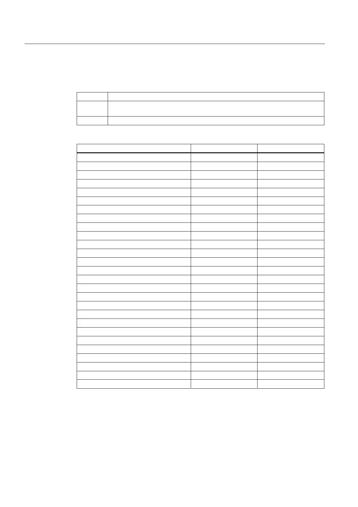
Comparison:
Range G70/G71 G700/G710
Parts program Parts program
R/W R/W
Display, decimal places (WCS) P/P P/P
Display, decimal places (MCS) G/G G/G
Feedrates G/G P/P
Positional data X, Y, Z P/P P/P
Interpolation parameters I, J, K P/P P/P
Circle radius (CR) P/P P/P
Polar radius (RP) P/P P/P
Pitch P/P P/P
Programmable FRAME P/P P/P
Settable FRAMES G/G P/P
Basic frames G/G P/P
Work offsets external G/G P/P
Axial preset offset G/G P/P
Operating range limit (G25/G26) G/G P/P
Protection zones P/P P/P
Tool offsets G/G P/P
Length-related machine data G/G P/P
Length-related setting data G/G P/P
Length-related system variables G/G P/P
GUD G/G G/G
LUD G/G G/G
PUD G/G G/G
R parameters G/G G/G
Siemens cycles P/P P/P
Jog/handwheel increment factor G/G G/G
Reference:
/PG/Programming Manual, Fundamentals; List of Addresses

 Loading...


