Brief description
1.2 Overview of auxiliary functions
Basic logic functions: Auxiliary Function Output to PLC (H2)
Function Manual, 11/2006, 6FC5397-0BP10-2BA0
11
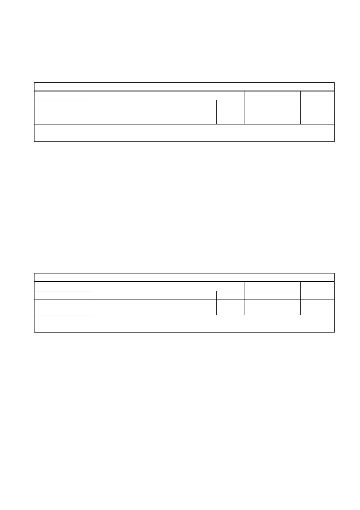
D functions
D (tool offset)
Address extension Value
Value range Meaning Value range Type Meaning Number
8)
- - - - - - 0 - 9 INT Selection of the tool
offset
1
Remarks:
Deselection of the tool offset with D0; the default is D1
Application
Selection of the tool offset.
Remarks
• Initial setting: D1
• After a tool change, the default tool cut can be parameterized via:
MD20270 $MC_CUTTING_EDGE_DEFAULT (Basic position of the tool cut without
programming)
• Deselection of the tool offset: D0
• D function-specific machine data:
MD22250 $MC_AUXFU_D_SYNC_TYPE (Output time of the D functions)
DL functions
DL (additive tool offset)
Address extension Value
Value range Meaning Value range Type Meaning Number
8)
- - - - - - 0 - 6 INT Selection of the
additive tool offset
1
Remarks:
The additive tool offset selected with DL refers to the active D number.
Application
Selection of the additive tool offset with reference to an active tool offset.
Remarks
• Initial setting: DL = 0
• DL values cannot be output to the PLC via synchronized actions.
• Default setting of the additive tool offset without an active DL function:
MD20272 $MC_SUMCORR_DEFAULT (basic setting of the additive offset without a
program)
• Deselection of the additive tool offset: DL = 0
• DL-function-specific machine data:
MD22252 $MC_AUXFU_DL_SYNC_TYPE (output time DL functions)
 Loading...


