Preface
Basic Functions
Function Manual, 11/2006, 6FC5397-0BP10-2BA0
5
Technical information
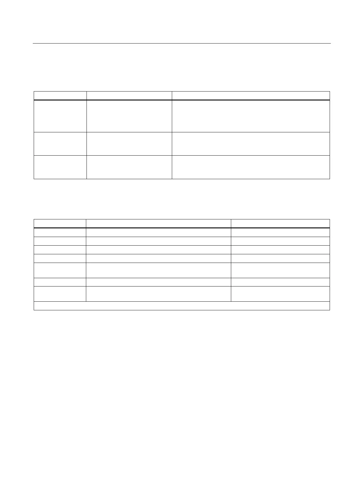
The following notation is used in this documentation:
Signal/Data Notation Example
NC/PLC interface
signals
... NC/PLC interface signal:
Signal data (signal name)
When the new gear step is engaged, the following NC/PLC
interface signals are set by the PLC program:
DB31, ... DBX16.0-16.2 (actual gear stage A to C)
DB31, ... DBX16.3 (gear is changed)
Machine data ... machine data:
<Type><Number> <Complete
Designator> (<Meaning>)
Master spindle is the spindle stored in the machine data:
MD20090 $MC_SPIND_DEF_MASTER_SPIND (Position of
deletion of the master spindle in the channel).
Setting Data ... Setting data:
<Type><Number> <Complete
Designator> (<Meaning>)
The logical master spindle is contained in the setting data:
SD42800 $SC_SPIND_ASSIGN_TAB[0] (Spindle number
converter).
Data types
The following elementary data types are used in the control system:
Type Meaning Value range
INT Signed integers -2147483646 ... +2147483647
REAL Figures with decimal point acc. to IEEE ±(2,2*10
-308
… 1,8*10
+308
)
BOOL Boolean values: TRUE/FALSE TRUE ≠ 0; FALSE = 0
CHAR 1 ASCII character corresponding to the code 0 … 255
STRING Character string, number of characters in [...], maximum of
200 characters
Sequence of values with 0 ... 255
AXIS Axis identifier Axis identifier for all channel axes
FRAME Geometrical parameters for translation, rotation, scaling,
and mirroring
Arrays can only be formed from similar elementary data types. Up to two-dimensional arrays are possible.
Quantity framework
Explanations concerning the NC/PLC interface are based on the absolute maximum number
of sequential components:
• Mode groups (DB11)
• Channels (DB21, etc.)
• Axes/spindles (DB31, etc.)
 Loading...


