Detailed description
2.4 Frames
Basic logic functions: Axes, coordinate systems, frames (K2)
Function Manual, 11/2006, 6FC5397-0BP10-2BA0
115
Alternatively, there is the option to enter this offset into the basic frame identified by machine
data
MD20184 $MC_TOCARR_BASE_FRAME_NUMBER
.
This option is available in the interests of compatibility with older software versions.
It is not recommended for use with new systems.
A frame offset as a result of a toolholder change becomes effective immediately on selection
of TCARR=.... A change in the tool length, on the other hand, only becomes effective
immediately if a tool is active.
A frame rotation does not take place on activation and a rotation which is already active is
not changed. As in case T (only the tool can be rotated), the position of the rotary axes used
for the calculation is dependent on the G code TCOFR/TCOABS and determined from the
rotation component of an active frame or from the entries $TC_CARRn. Activation of a frame
changes the position in the workpiece coordinate system accordingly, without compensating
movement by the machine itself.
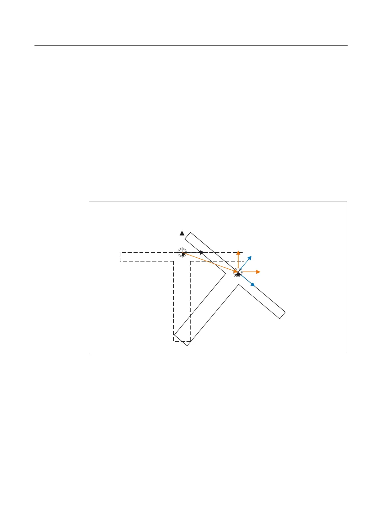
The ratios are shown in the figure below:
2ULJLQDOSRVLWLRQRIWKH
FRRUGLQDWHV\VWHP
2ULJLQDOSRVLWLRQRIWDEOH
3RVLWLRQRIWDEOH
DIWHUURWDWLRQ
3RVLWLRQRIFRRUGLQDWHV\VWHP
DIWHU7&$55
3RVLWLRQRIFRRUGLQDWHV\VWHP
DIWHU3$527
Figure 2-22 Frame on activation of a rotary table with TCARR
With kinematics of type M (tool and table are each rotary around one axis), the activation of
a toolholder with TCARR simultaneously produces a corresponding change in the effective
tool length (if a tool is active) and the zero offset.
 Loading...


