SVAN 979 User Manual - Appendixes
Note: The SV 55 must be connected to the SVAN 979 USB Host port and proper operation of this
port must be set-up in the instrument’s setup Menu before!
The SV 55 - DB 09 F - pin female connector pin-out is given below.
Table C.5.6. SV 55 interface description
PC RS 232,
9 - pin connector
Signal name
SV 55 connector
(DB 09 F)
Pin number
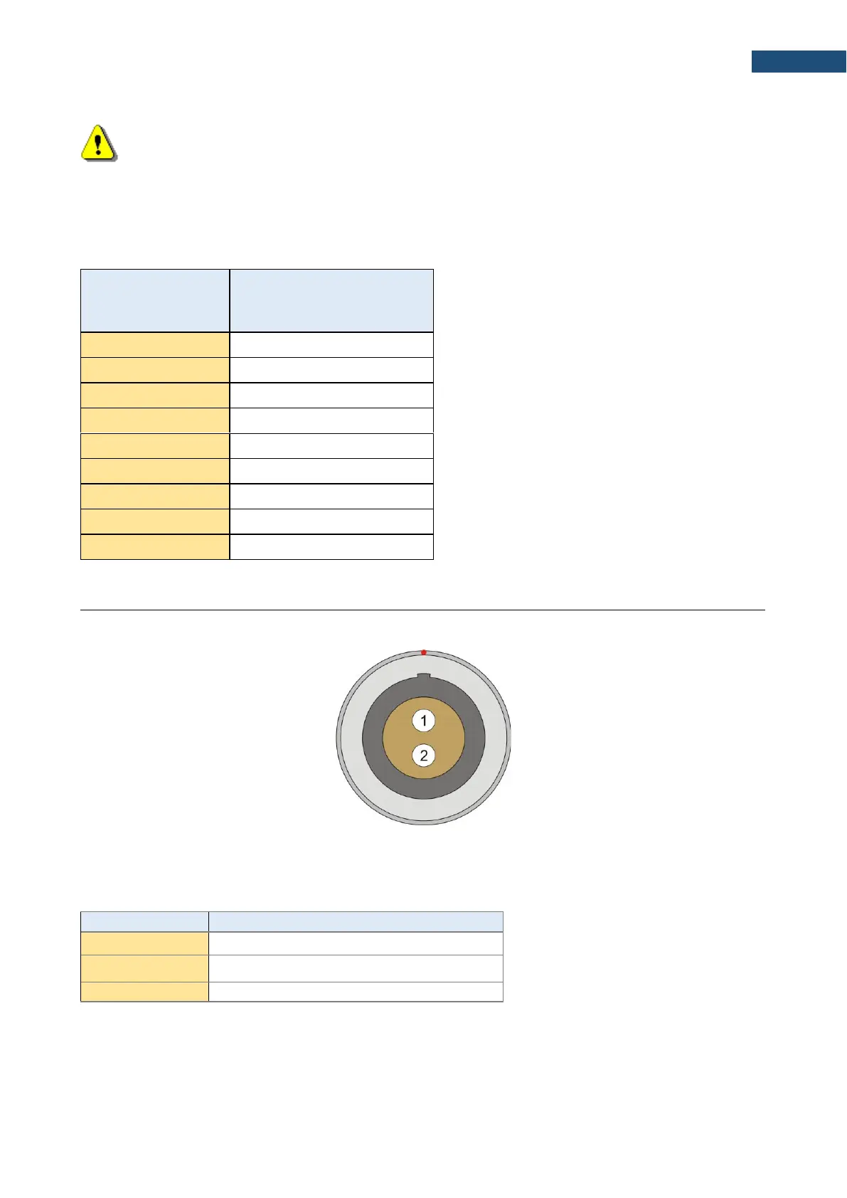
I/O – User programmable Analogue Outputs, Digital Input / Output connector
LEMO type ENG0B302 (outer view)
Table C.5.7. Pin out of the LEMO ENG0B302
The user may set-up the I/O mode in the screen <Menu> / Instrument / Multifunction I/O:
1. I/O Mode: Analog Out. In this mode, analogue signal from the instrument is fed to it’s I/O connector, with
following user-selectable options: