Communications Teledyne API T703/T703U Calibrator Operation Manual
108
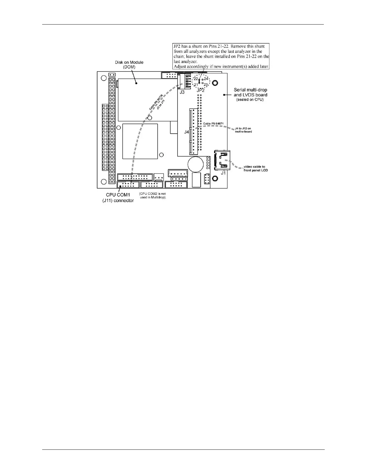
Figure 5-3: Jumper and Cables for Multidrop Mode
4. Close the instrument.
5. Referring to Figure 5-4, use straight-through DB9 male-DB9 female cables to
interconnect the host RS232 port to the first instrument‟s RS232 port; then
from the first instrument‟s COM2 port to the second instrument‟s RS232 port;
from the second instrument‟s COM2 port to the third instrument‟s RS232 port,
etc., connecting in this fashion up to eight instruments, subject to the distance
limitations of the RS-232 standard.
6. On the rear panel of each instrument, adjust the DCE DTE switch so that the
green and the red LEDs (RX and TX) of the COM1 connector (labeled
RS232) are both lit. (Ensure you are using the correct RS-232 cables
internally wired specifically for RS-232 communication).
7. BEFORE communicating from the host, power on the instruments and check
that the Machine ID (Section 5.6.2) is unique for each.
a. In the SETUP Model menu, use SETUP>MORE>COMM>ID. The default ID
is typically either the model number or “0”.
b. To change the identification number, press the button below the digit to be
changed.
c. Press/select ENTR to accept the new ID for that instrument.
8. Next, in the SETUP>MORE>COMM>COM1 menu (do not use the COM2
menu for multidrop), edit the COM1 MODE parameter as follows: press/select
EDIT and set only QUIET MODE, COMPUTER MODE, and MULTIDROP
MODE to ON. Do not change any other settings.
9. Press/select ENTER to accept the changed settings, and ensure that COM1
MODE now shows 35.