Teledyne API T703/T703U Calibrator Operation Manual Getting Started
21
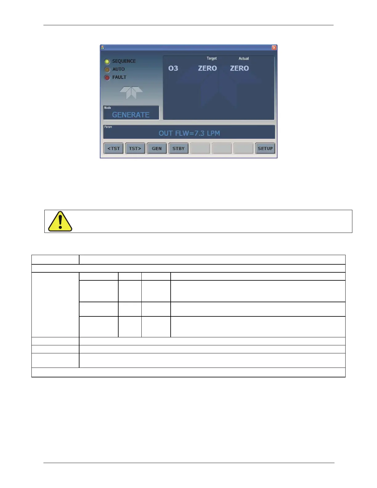
Figure 3-2: Display Screen and Touch Control
The front panel liquid crystal display (LCD) screen includes touch control. Upon
calibrator start-up, the LCD shows a splash screen and other initialization
indicators before the main display appears.
Table 3-1: Display Screen and Touch Control Description
LEDs indicating the states of the calibrator:
Unit is operating in STANDBY mode.
This LED is lit when the instrument is actively producing calibration
gas (GENERATE mode).
This LED is lit only when the calibrator is performing an automatic
calibration sequence.
The calibrator is warming up and therefore many of its subsystems
are not yet operating within their optimum ranges. Various warning
messages may appear in the Param field.
Gas concentrations, Cal gas MFC and Diluent MFC values with unit of measure
Displays the name of the calibrator‟s current operating mode (default is STANDBY at initial startup).
Displays a variety of informational messages such as warning messages, operational data, test function
values and response messages during interactive tasks.
Touchscreen control: row of eight buttons with dynamic, context sensitive labels; buttons are blank when inactive/inapplicable.
Figure 3-3 shows how the front panel display is mapped to the menu charts that
are illustrated throughout this manual. The Mode, Param (parameters), and
Target/Actual (gas concentration) fields in the display screen are represented
across the top row of each menu chart. The eight touch control buttons along the
bottom of the display screen are represented in the bottom row of each menu
chart.
CAUTION – Avoid Damaging Touchscreen
Do not use hard-surfaced instruments such as pens to operate the touch screen buttons.