Teledyne API T703/T703U Calibrator Operation Manual Operating the Calibrator
79
Manual Calibration of the TEST Channel Configured for Voltage Ranges 4.9.2.3.
For highest accuracy, the voltages of the analog outputs can be manually
calibrated.
NOTE:
The menu for manually adjusting the analog output signal level will only appear if the AUTO-CAL
feature is turned off for the channel being adjusted (see Section 4.9.2.1)
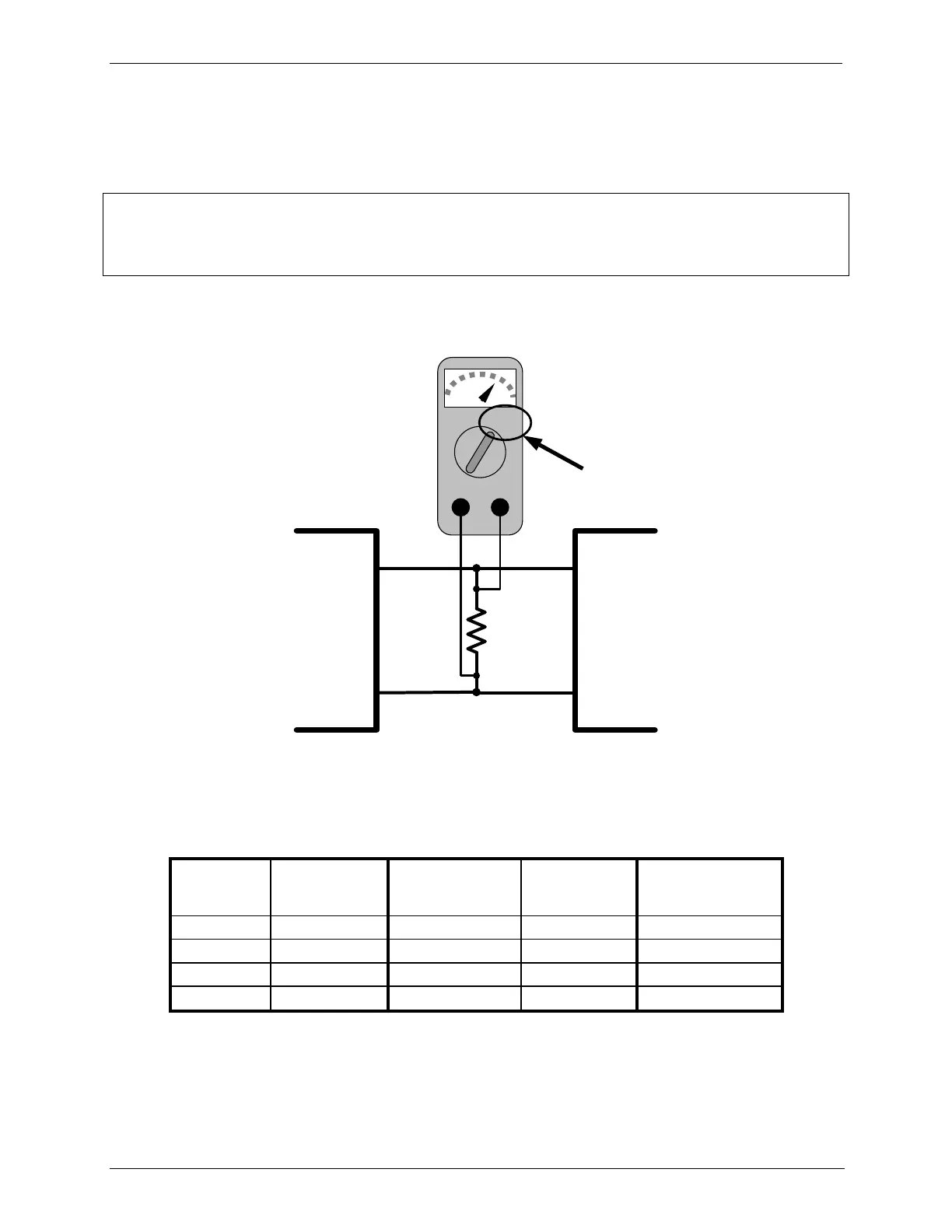
Calibration is performed with a voltmeter connected across the output terminals
(See Figure 4-2) and by changing the actual output signal level using the front
panel menu buttons in 100, 10 or 1 count increments.
Recording
Device
V IN +
V IN -
ANALYZER
V OUT +
V OUT -
250 Ω
Volt
Meter
Figure 4-3: Setup for Calibrating the TEST CHANNEL
Table 4-10: Voltage Tolerances for the TEST CHANNEL Calibration
MINIMUM
ADJUSTMENT
(1 count)