Calibration and Verification Teledyne API T703/T703U Calibrator Operation Manual
140
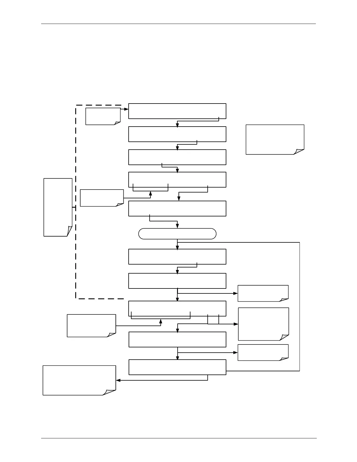
Performing an Output Gas Flow Calibration 6.4.2.2.
During the PHOTO FLOW calibration, the T703/T703U software automatically
turns the DC pump downstream from the photometer OFF and the AC dry air
pump ON. Once the PHOTO FLOW has been calibrated (Section 8.4.1 – menu
sequence included here for continuity), the next step is to adjust the “ACTUAL
PHOTO FLOW” values to match the flow measured by the external flow meter in
order to calibrate the output gas flow (ACTUAL OUTPUT FLOW), as follows:
STANDBY ACT =STANDBY
<TST TST> GEN STBY SEQ SETUP
Make sure that the
calibrator is in
standby mode.
SETUP X.X PRIMARY SETUP MENU
O3 SEQ CFG CLK PASS MORE EXIT
SETUP X.X SECONDARY SETUP MENU
COMM VARS DIAG EXIT
SETUP X.X ENTER PASSWORD
8 1 8 ENTR EXIT
Toggle to enter the
correct PASSWORD
DIAG SIGNAL I/O
PREV NEXT ENTR EXIT
DIAG PHOTO FLOW SENSOR CAL
PREV NEXT ENTR EXIT
Continue pressing NEXT until ...
An external flow
meter is needed to
perform this
operation.
DIAG FCAL ACTUAL PHOTO FLOW: 1.000 LPM
1 .0 0 0 0 ENTR EXIT
Adjust this value by
toggling these buttons to
match the actual flow as
measured by the external
flow meter.
EXIT discards the user-
adjusted flow values.
ENTR accepts the new
flow values and
calibrates the actual
output flow.
DIAG FCAL WAITING FOR FLOW
DIAG FCAL WAITING FOR FLOW
Do NOT press the ENTR button at
this point.
Doing so will cause the slope
applied to the Output Flow reading
be recalculated.
DIAG FCAL ACTUAL OUTPUT FLOW: 1.000 LPM
1 .0 0 0 0 ENTR EXIT
Instrument is
calibrating the actual
output flow.
Instrument is
calibrating the photo
flow.
This
portion of
the
procedure
was
performed
in the
preceding
section