Principles of Operation Teledyne API T703/T703U Calibrator Operation Manual
188
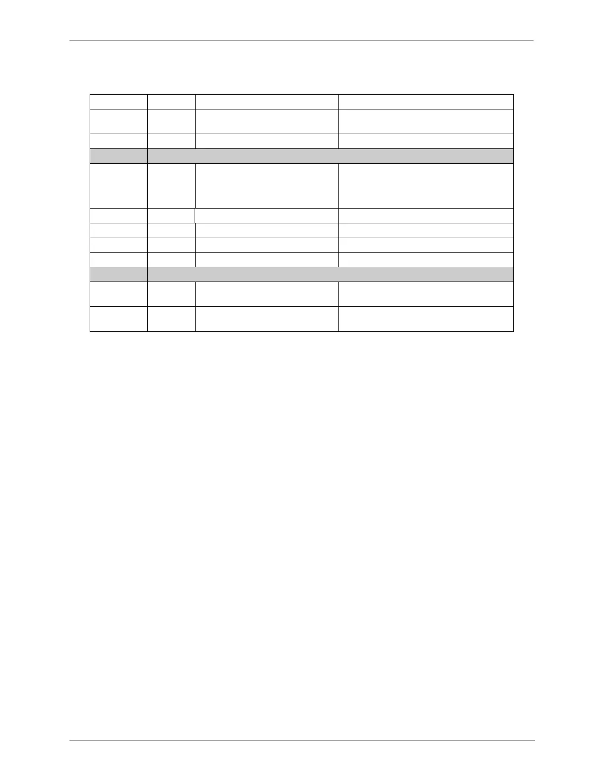
Table 9-1: Relay Board Status LEDs
Watchdog Circuit; I
2
C bus
operation.
Blinks when I
2
C bus is operating properly
Zero Air Pump (option) Status
When lit the zero air AC pump is running.
Photometer Meas/Ref Valve
Status
When lit the valve open to the Measure
gas path; when not lit while instrument is
running, the valve is open to the
Reference gas path.
Zero Air Shutoff Valve (option) Status
When lit, ZA shutoff valve open.
When lit, O
3
pump running
T703U Divert Valve Status
when lit, divert valve open.
T703U O
3
Generator Valve Status
When lit, O
3
generator valve open.
Photometer Lamp Heater Status
When lit the photometer UV lamp heater
is on
When lit the O
3
generator UV lamp heater
is on
Relay PCA Watchdog Indicator (D1) 9.2.3.4.
The most important of the status LEDs on the relay board is the red I
2
C Bus
watchdog LED. It is controlled directly by the calibrator‟s CPU over the I
2
C bus.
Special circuitry on the relay PCA watches the status of D1. Should this LED
ever stay ON or OFF for 30 seconds (indicating that the CPU or I
2
C bus has
stopped functioning) this Watchdog Circuit automatically shuts all valves and
turns off all heaters and lamps.