Teledyne API T703/T703U Calibrator Operation Manual Communications
109
10. Press/select SET> to go to the COM1 BAUD RATE menu and ensure it reads
the same for all instruments (edit as needed so that all instruments are set at
the same baud rate).
NOTE:
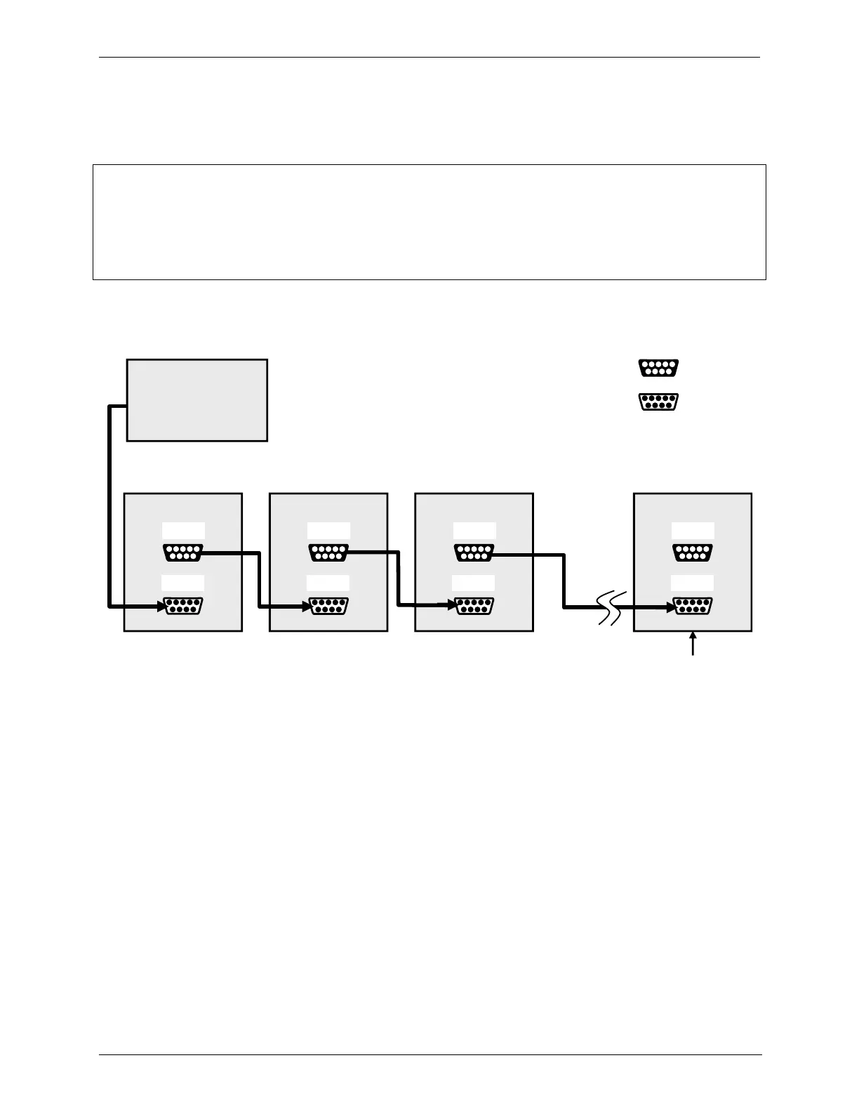
Teledyne API recommends setting up the first link, between the Host and the first instrument and
testing it before setting up the rest of the chain.
The (communication) Host instrument can address only one instrument at a time, each by its
unique ID (see Step 7 above).
Ensure jumper is
installed between
JP2 pins 21 22 in
last instrument of
multidrop chain.
Figure 5-4: RS232-Multidrop PCA Host/Calibrator Interconnect Diagram
5.4. RS-485 CONFIGURATION OF COM2
As delivered from the factory, COM2 is configured for RS-232 communications.
This port can be reconfigured for operation as a non-isolated, half-duplex RS-485
port. To configure the instrument for RS-485 communication, please contact the
factory. (Using COM2 for RS-485 communications disables the optional USB
com port).
5.5. REMOTE ACCESS VIA THE USB PORT (OPTION)
The calibrator can be connected to a personal computer by direct connection
through their respective USB ports.