Teledyne API T703/T703U Calibrator Operation Manual Principles of Operation
183
range sensor. This data is used by the CPU when calculating the O
3
concentration inside the absorption tube. This value is displayed on the front
panel as a test measurement called PHOTO SPRESS. Note that this value is
converted to units of Inches of Mercury (IN-HG-A) when displayed on the front
panel.
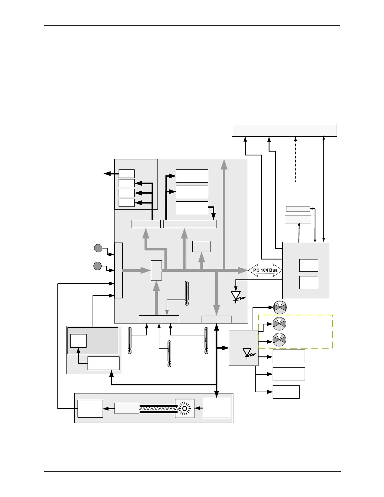
9.2. ELECTRONIC OPERATION
OVERVIEW 9.2.1.
Photometer
Lamp Power
Supply
Photometer
Detector
Preamp
Photometer
Detector
O
3
Generator
Analog Outputs
Aout 1
Aout 4
Analog Outputs
(D/A)
External Digital I/O
Power Up
Circuit
Sensor Inputs
PC 104
CPU Card
Disk on
Module
Flash
Chip
Aout 3
Aout 2
TEST
CHANNEL
OUTPUT
Status Outputs
1 - 8
Control Outputs
1 - 12
Control Inputs
1 - 12
CPU
Status
LED
I
2
C Bus
O
3
Generator
Lamp Supply
Thermistor Interface
Box
Temperature
Photometer Sample Gas
Pressure Sensor
O
3
Generator Input
Pressure Sensor
UV
Lamp
A/D
Converter
RELAY
PCA
I
2
C
Status
LED
Photometer
UV Lamp
Temperature
O3 Generator
UV Lamp
Temperature
Photometer Sample Gas
Temperature
Photometer
M/R Valve
COM2
Female
RS232
Male
Etherne t
USB COM
port
COM1 (RS-232 only)
COM2 (RS-232 or RS-485)
or USB
Divert Valve
O
3
Gen Valve
Photometer
Pump
Photometer
Lamp Heater
O
3
Generator
Lamp Heater
In T703U only.
Figure 9-3: Electronic Block Diagram
The core of the calibrator is a microcomputer (referred to as the CPU) that
controls various internal processes, interprets data, makes calculations, and
 Loading...