Teledyne API T703/T703U Calibrator Operation Manual Operating the Calibrator
91
CONFIGURING LEVEL STATUS BLOCKS 4.12.6.
There are two STATUS BLOCKS associated with LEADS LEVELS.
BLOCK 1: This block corresponds to the physical CONTROL OUTPUT
connections located on the back panel of the T703 (see Figure 3-4, Figure
3-12 and Section 3.2.5).
BLOCK 2: The second status block does not correspond to any physical
output but is used to communicate status over the serial data port
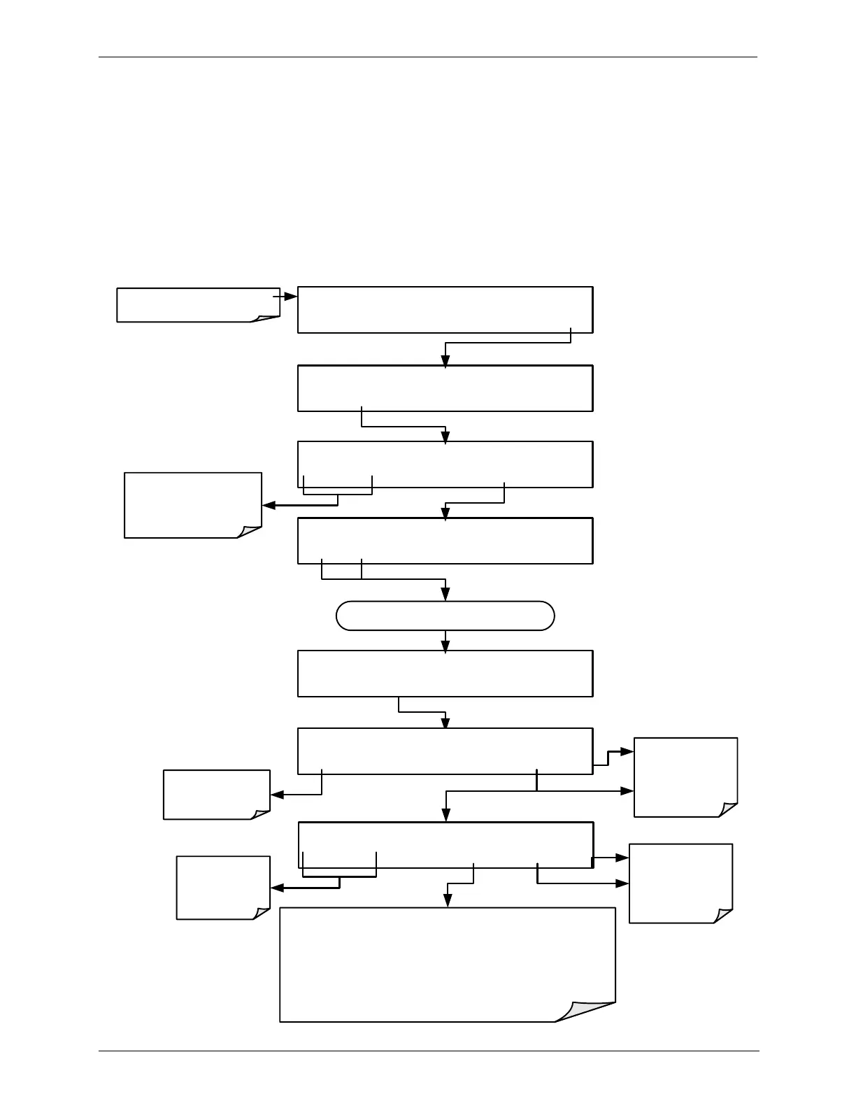
To configure the either of the STATUS BLOCKS, press:
SETUP X.X [LEVEL ID] )[Gas/Conc.],[Status Block Set’g]
PREV NEXT INS DEL EDIT PRNT EXIT
SETUP X.X LEVEL NUMBER:12
<SET SET> EDIT EXIT
SETUP X.X STATUS BLOCK 2:DISABLED
<SET SET> EDIT EXIT
Continue pressing SET> until Desired
Status Block is reached
SETUP X.X STATUS BLOCK 2:[0]0000000
<CH CH> [0] ENTER EXIT
EXIT discards the
new setting
ENTR accepts the
new setting
SETUP X.X STATUS BLOCK 2:OFF
OFF ENTER EXIT
Turns the CC
input ON/OFF
EXIT discards the
new setting
ENTR accepts the
new setting
Toggle to turn the selected bit ON/OFF (0 or 1).
Each bit shown on the display represents one of the control
output pins located on the back of the calibrator.
The left most bit is Bit 1, the next bit to the right, bit 2,
progressing rightward to bit 8.
Moves the
cursor one
character left or
right.
STANDBY ACT =STANDBY
<TST TST> GEN STBY SEQ SETUP
Make sure that the calibrator
is in standby mode.
SETUP X.X PRIMARY SETUP MENU
O3 LEVL SEQ CFG CLK PASS MORE EXIT
Toggle to scroll to the
LEVEL for editing.