General Troubleshooting & Service Teledyne API T703/T703U Calibrator Operation Manual
162
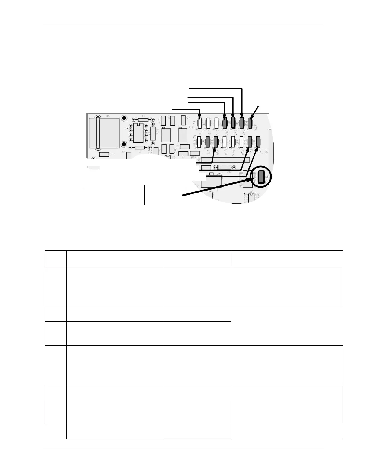
If D1 is blinking, then the other LEDs can be used in conjunction with DIAG
Menu Signal I/O to identify hardware failures of the relays and switches on the
Relay.
Troubleshooting with Relay Board Status LEDs 8.3.2.2.
D15 (Green) - Photometer Lamp Heater
D16 (Green) – O
3
Generator Lamp Heater
D7 (Green) – Photometer Meas/Ref Valve
D1 (RED)
Watchdog
Indicator
T703U only:
D10 (Green)
O
3
Divert Valve
T703U only: D11 (Green) – O
3
Generator Valve
D2 (Yellow) – Zero Air Pump Option
D8 (Green) – Zero Air Shutoff Valve Option
Figure 8-3: Relay PCA Status LEDs Used for Troubleshooting
Table 8-5: Relay PCA Status LED Failure Indications
AC- powered Zero Air Pump
(option) status
Pump should start /stop. If not:
Failed pump
Failed AC Relay on Relay PCA
Failed Relay PCA
Faulty AC Power Supply (PS2)
Faulty Connectors/Wiring
Photometer Meas/Ref Valve status
Valve should audibly change states. If not:
Failed Valve
Failed Relay Drive IC on Relay PCA
Failed Relay PCA
Faulty +12 VDC Supply (PS2)
Faulty Connectors/Wiring
Zero Air Shutoff Valve (option) status
DC-powered O
3
Pump status
Pump should start /stop. If not:
Failed pump
Failed Drive IC on Relay PCA
Failed Relay PCA
Faulty +12 VDC Supply (PS2)
Faulty Connectors/Wiring
T703U Divert Valve status
Valve should audibly change states. If not:
Failed Valve
Failed Relay Drive IC on Relay PCA
Failed Relay PCA
Faulty +12 VDC Supply (PS2)
Faulty Connectors/Wiring
T703U O
3
Generator Valve status
Voltage displayed should change. If not:
Failed Heater
 Loading...