Operating the Calibrator Teledyne API T703/T703U Calibrator Operation Manual
72
TEST Channel Voltage Range Configuration 4.9.1.3.
In its standard configuration the analog outputs is set to output a 0 – 5 VDC
signals. Several other output ranges are available (see Table 7-5). Each range
has is usable from -5% to + 5% of the rated span.
Table 4-9: Analog Output Voltage Range Min/Max
The default offset for all ranges is 0 VDC.
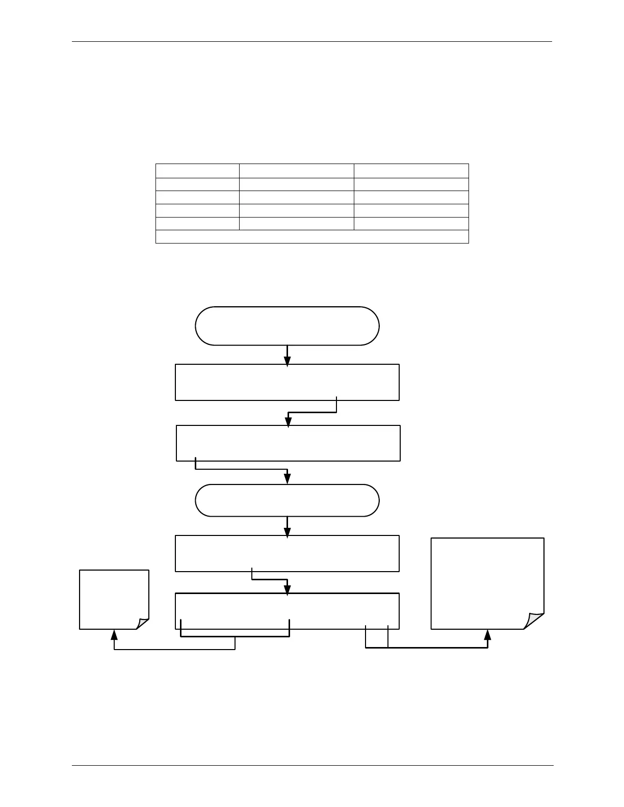
To change the output range, press,
DIAG AIO AOUTS CALIBRATED: NO
SET> CAL EXIT
From the
AIO CONFIGURATION SUBMENU
DIAG ANALOG I/O CONFIGURATION
PREV NEXT ENTR EXIT
Continue pressing SET> until you reach the
output to be configured
DIAG AIO TEST_OUTPUT: 5V, OVR, NOCAL
<SET SET> EDIT EXIT
DIAG AIO TEST_OUTPUT: RANGE: 5V
0.1V 1V 5V 10V ENTR EXIT
These buttons
set the signal
level and type
of the selected
channel
Pressing ENTR records
the new setting and
returns to the previous
menu.
Pressing EXIT ignores the
new setting and returns to
the previous menu.