Getting Started Teledyne API T703/T703U Calibrator Operation Manual
34
3.3. PNENUMATIC CONNECTIONS
CAUTION!
Do not operate this instrument until you’ve removed dust plugs from inlet and
outlet/exhaust ports on the rear panel!
OPTIONAL
Teledyne Instruments
MODEL 701
Zero Gas Generator
T703/T703U
Photometric
O
3
Calibrator
CAL GAS OUT
VENT
DRY AIR IN
CAL GAS OUT
Teledyne Instruments
T-Series Gas Analyzer
Sample Inlet
ZERO AIR IN
Desiccant
Ambient
Air
Teledyne Instruments
T-Series Gas Analyzer
Sample Inlet
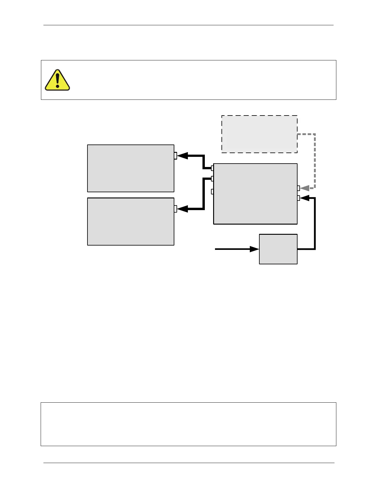
Figure 3-13: Basic Pneumatic Setup
DRY AIR IN 3.3.1.
When using the internal zero air pump, a source of dry air should be connected to
the port labeled „Dry Air In‟ on the rear panel. This air should be supplied at
atmospheric pressure. The supplied air should have a dew point of –20 C or
less.
Teledyne API can supply an optional desiccant cartridge that can be used to
supply dry air to the T703/T703U.
ZERO AIR IN 3.3.2.
An external pressurized source of zero air can be supplied at the „Zero Air” port
on the rear panel. This is the standard configuration when the zero air pump is
not installed. This zero air should be scrubbed of ozone and have a dew point of -
20 C or less. The pressure of the zero air should be regulated to 20-35 psig.
NOTE
When connecting an external source of zero air to an T703 with an internal zero air pump installed,
the zero air pump should be disabled.
The “ZA_PUMP_ENABLE” VAR (see Section 4.10) should be set to OFF.