Calibration and Verification Teledyne API T703/T703U Calibrator Operation Manual
138
CALIBRATING THE PHOTOMETER’S SAMPLE GAS FLOW 6.4.1.
NOTE
The procedure described in this section requires an independent, calibrated gas flow
meter/monitor be connected to the EXHAUST fitting on the back of the T703/T703U.
During the PHOTO FLOW calibration, the T703/T703U software automatically
turns the DC pump downstream from the photometer ON. PHOTO FLOW
calibration is followed by ACTUAL OUTPUT FLOW (output gas flow)
calibration (Section 6.4.2).
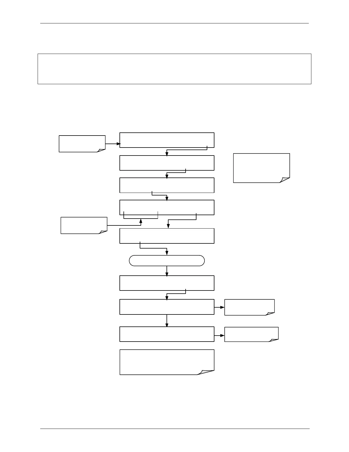
To perform a PHOTO FLOW calibration, press:
STANDBY ACT =STANDBY
<TST TST> GEN STBY SEQ SETUP
Make sure that the
calibrator is in standby
mode.
SETUP X.X PRIMARY SETUP MENU
O3 SEQ CFG CLK PASS MORE EXIT
SETUP X.X SECONDARY SETUP MENU
COMM VARS DIAG EXIT
SETUP X.X ENTER PASSWORD
8 1 8 ENTR
EXIT
Toggle to enter the correct
PASSWORD
DIAG SIGNAL I/O
PREV NEXT ENTR EXIT
DIAG PHOTO FLOW SENSOR CAL
PREV NEXT ENTR EXIT
Continue pressing NEXT until ...
An external flow meter
is needed to perform
this operation.
DIAG FCAL ACTUAL PHOTO FLOW: 1.000 LPM
1 .0 0 0 0 ENTR EXIT
DIAG FCAL WAITING FOR FLOW
The next step in the menu is to adjust this
reading to match the flow value as measured
by the external flow meter. (See section on
“Calibrating the Output Gas Flow”).
At this point the photo
flow has been calibrated.
Instrument is calibrating
the photo flow.