General Troubleshooting & Service Teledyne API T703/T703U Calibrator Operation Manual
164
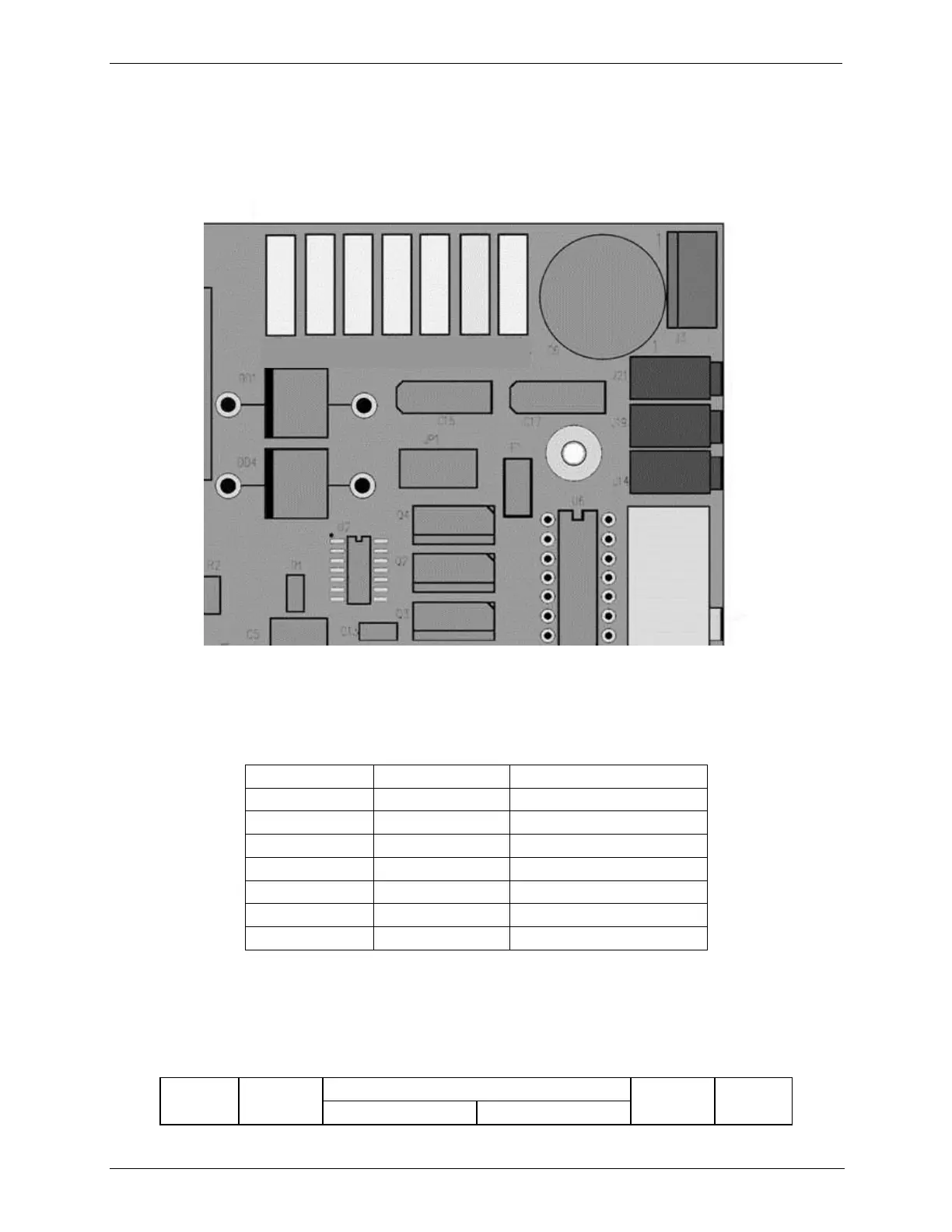
associated test points on the relay PCA follow a standard color-coding scheme as
defined in the following table.
TP1 TP2 TP3 TP4 TP5 TP6 TP7
DGND +5V AGND +15V -15V +12R 12V
Figure 8-4: Location of DC Power Test Points on Relay PCA
Table 8-6: DC Power Test Point and Wiring Color Codes
A voltmeter should be used to verify that the DC voltages are correct per the
values in the table below, and an oscilloscope, in AC mode, with band limiting
turned on, can be used to evaluate if the supplies are producing excessive noise (>
100 mV p-p).
Table 8-7: DC Power Supply Acceptable Levels
CHECK RELAY PCA TEST POINTS