Teledyne API T703/T703U Calibrator Operation Manual Calibration and Verification
133
6.3. CALIBRATING GAS PRESSURE SENSORS
The T703 Calibrator has two sensors that monitor the pressure of the gases
flowing through the instrument: a Regulator pressure sensor and a Photometer
Sample Gas pressure sensor. The T703U also has those two sensors plus one
more: an O
3
Generator Regulator pressure sensor. The data collected by these
sensors are used to compensate the final concentration calculations for changes in
atmospheric pressure and are stored in the CPU‟s memory as test functions:
Table 6-1: T703/T703U Pressure Sensors
PRESSURE MONITOR
MEASUREMENT POINT
Regulator Pressure Sensor
Capped fitting on backside of regulator
assembly. See Figure 6-5.
Photometer Sample Gas
Pressure Sensor
Use monitor to measure ambient
atmospheric pressure at the calibrator‟s
location.
(T703U only) O
3
Generator
Regulator Pressure Sensor
Capped fitting on O
3
Generator Regulator
assembly. See Figure 6-6.
GAS PRESSURE SENSOR CALIBRATION SET UP 6.3.1.
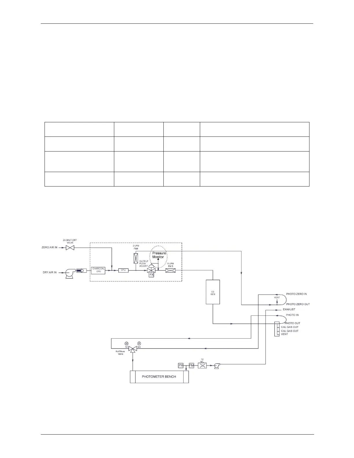
The procedures described in this section require an independent, calibrated
pressure meter/monitor to be attached at the location shown in Figure 6-3 for
T703, or at the locations shown in Figure 6-4 for T703U.
Figure 6-3: Pressure Calibration Monitor Point – T703



 To Next Page