Operating the Calibrator Teledyne API T703/T703U Calibrator Operation Manual
84
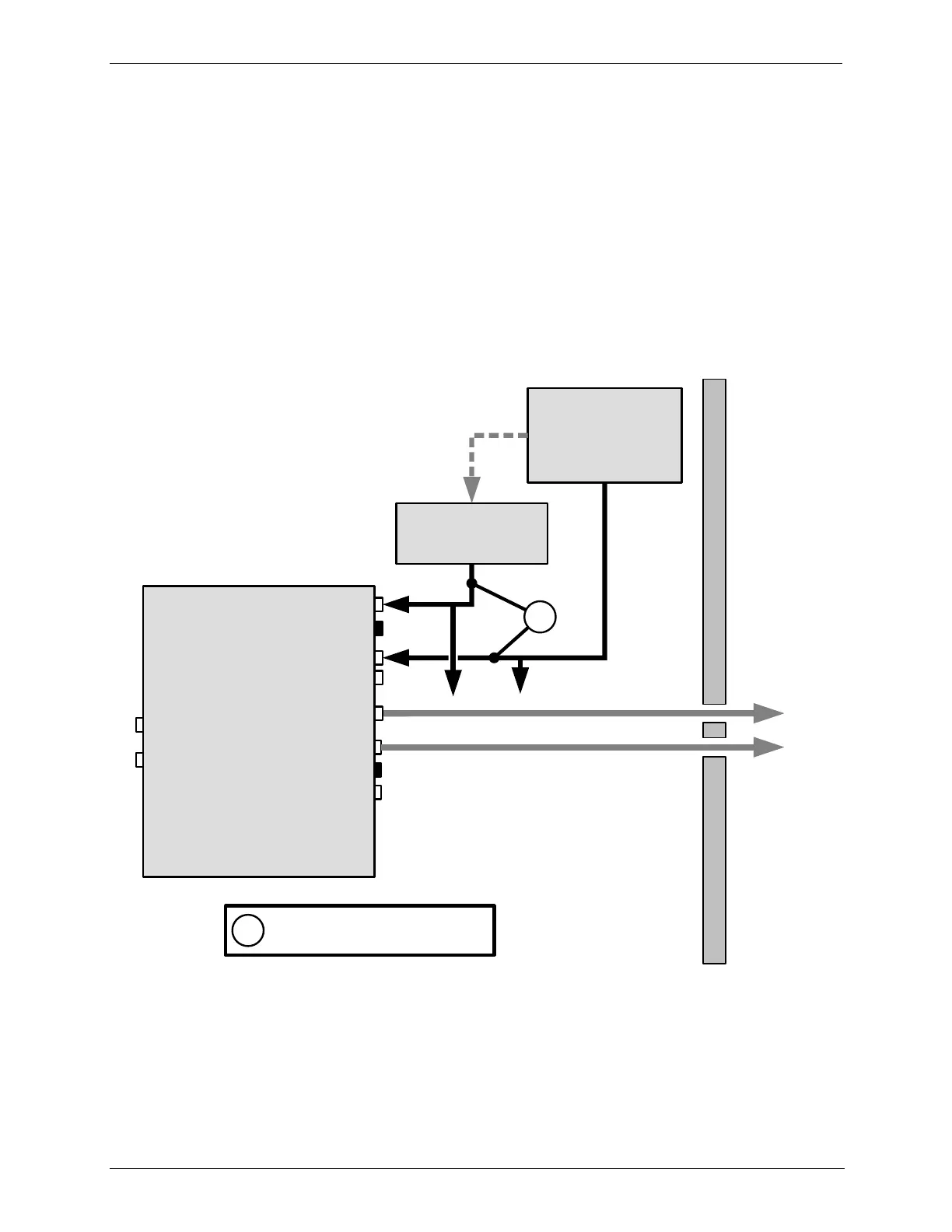
SET UP FOR OPERATION AS AN O
3
PHOTOMETER 4.11.1.
To convert the T703/T703U from an O
3
calibrator to and O
3
photometer:
1. Remove the two loop-back tubing assemblies on the rear panel connected to
the „PHOTO IN‟ and „PHOTO ZERO IN‟ fittings.
2. Connect the ozone source to be measured to the „PHOTO IN‟ fitting.
This gas must be supplied at atmospheric pressure.
3. Connect a reference gas (Zero Air) for the photometer to the „PHOTO ZERO
IN.‟
This gas must be supplied at atmospheric pressure. To avoid
interference effects, the reference gas should be from the same source
than is being used to feed the ozone generator that is being assayed.
EXHAUST line: Max Length=3 meters ( or 10 feet)
Enclosure Wall
Photometric
O
3
Calibrator
VENT
CAL GAS OUT
DRY AIR IN
CAL GAS OUT
PHOTOMETER OUTLET
PHOTOMETER INLET
PHOTOMETER ZERO IN
PHOTOMETER ZERO OUT
EXHAUST
ZERO AIR IN
REFERENCE GAS
SOURCE
Capped
O
3
SOURCE TO BE
MEASURED
Capped
Minimum input gas flow for
Photometer is 800 cc
3
/min
1
1
--(vents)--
Figure 4-4: Set up to Measure an External O
3
Source