Calibration and Verification Teledyne API T703/T703U Calibrator Operation Manual
136
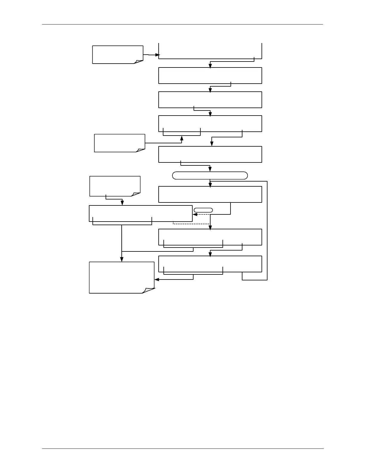
DIAG PCAL SAMPLE PRESS: 28.00 IN-HG-A
0 2 8 .0 0 ENTR
EXIT
STANDBY ACT =STANDBY
<TST TST> GEN STBY SEQ SETUP
Make sure the calibrator is
in STANDBY mode.
SETUP X.X PRIMARY SETUP MENU
O3 SEQ CFG CLK PASS MORE EXIT
SETUP X.X SECONDARY SETUP MENU
COMM VA DIAG EXIT
SETUP X.X ENTER PASSWORD
8 1 8 ENTR
EXIT
Toggle to enter the correct
PASSWORD
DIAG SIGNAL I/O
PREV NEXT ENTR EXIT
DIAG PRESSURE CALIBRATION
PREV NEXT ENTR EXIT
Continue pressing NEXT until ...
DIAG PCAL REGULATOR PRESS: 00.56 PSIG
0 0 0 .5 6 ENTR
EXIT
Toggle to change the calibrator’s
pressure display to match the
value measured by the pressure
monitor installed in-line with the
pressure sensor being calibrated.
DIAG PCAL O3 PRESS: 15.02 PSIG
0 1 5 .0 2 ENTR
EXIT
703U only
If the unit is a T703U, the
menu item, O3 PRESS, for
O
3
Regulator Pressure
displays first.
5. Turn OFF the calibrator, remove the pressure monitor, replace the cap on the
pressure measurement fitting.
6.4. GAS FLOW CALIBRATION
The T703/T703U has two gas flow characteristics that affect its performance: the
flow of gas through the sample chamber of the instrument‟s photometer and the
total gas flow being output. While both are stored in the calibrator‟s memory and
used to compensate the final concentration calculations for changes in
atmospheric pressure, they are calculated quite differently:
CALCULATING THE PHOTOMETER SAMPLE GAS FLOW RATE
This flow rate is measured directly by a flow sensor located pressure / flow
sensor PCA. A slope factor, stored in the calibrator‟s memory the last time a
PHOTO FLOW calibration operation (see Section 6.4.1) was performed, is and
applied to the reading from that sensor.