General Troubleshooting & Service Teledyne API T703/T703U Calibrator Operation Manual
170
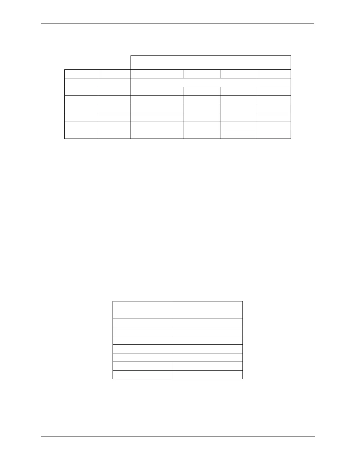
Table 8-9: Analog Output Test Function - Nominal Values Voltage Outputs
FULL SCALE OUTPUT OF VOLTAGE RANGE
(see Section 4.9.1.3)
If one or more of the steps fails to be within these ranges, it is likely that there has
been a failure of the either or both of the DACs and their associated circuitry on
the motherboard.
Status Outputs 8.4.9.3.
To test the status output electronics:
1. Connect a jumper between the “D“ pin and the “” pin on the status output
connector.
2. Connect a 1000 ohm resistor between the “+” pin and the pin for the status
output that is being tested.
3. Connect a voltmeter between the “” pin and the pin of the output being
tested (see table below).
4. Under the DIAG> SIGNAL I/O menu (See Section8.1.3), scroll through the
inputs and outputs until you get to the output in question.
5. Alternately, turn on and off the output noting the voltage on the voltmeter.
It should vary between 0 volts for ON and 5 volts for OFF.
Table 8-10: Status Outputs Check