Getting Started Teledyne API T703/T703U Calibrator Operation Manual
40
SETTING THE OUTPUT FLOW RATE 3.4.7.
The output flow rate must consider both the total gas flow requirements of all
analyzers connected to the output manifold and the minimum output flow of the
O
3
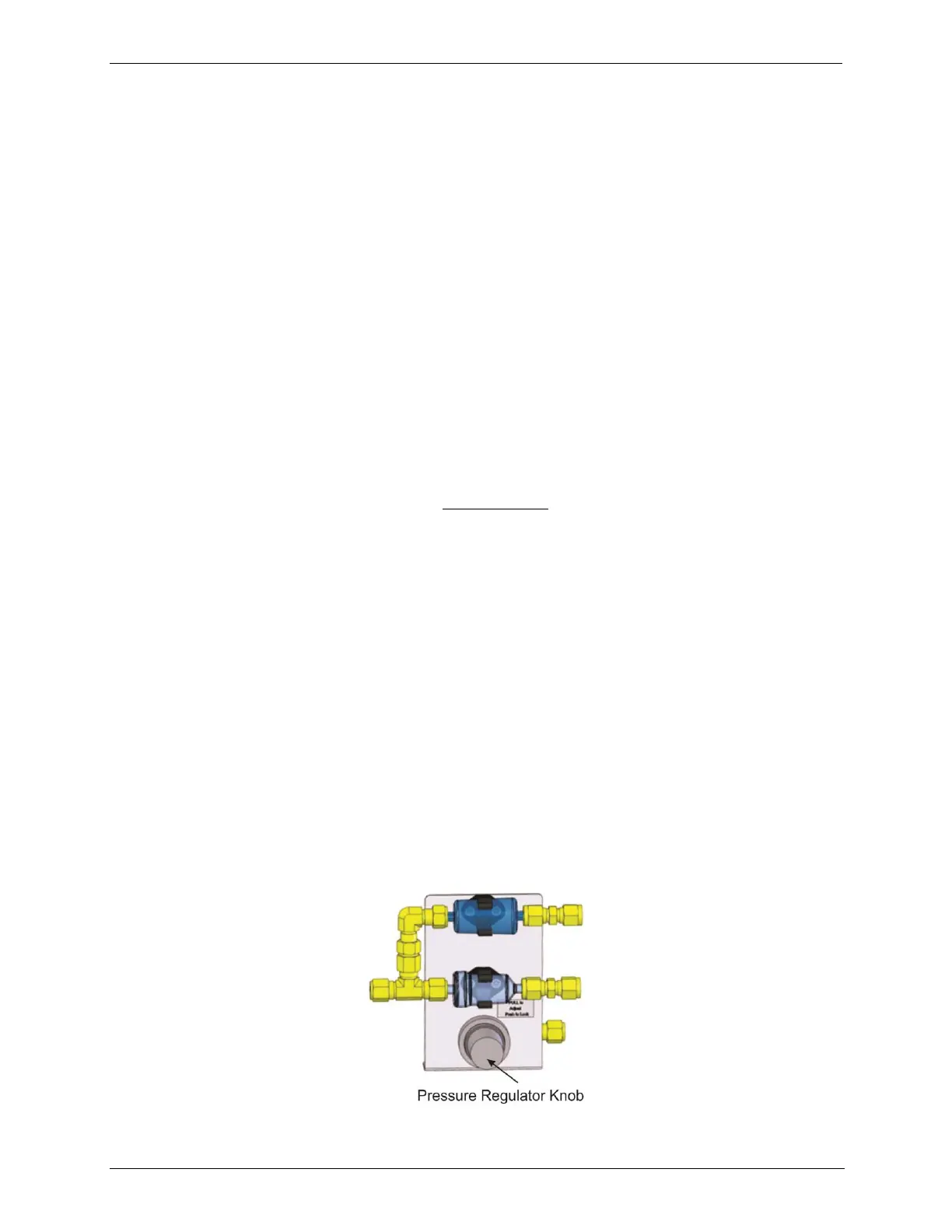
generator. Figure 3-14 shows a close-up of the regulator assembly.
Calculating Output Flow Rate 3.4.7.1.
First, add the sum of the flow requirements of all of the instruments to which the
T703/T703U will be supplying calibration gas plus 1 LPM excess flow. For
example, if the T703 is expected to supply calibration gas mixtures
simultaneously to two analyzers, each requiring 0.8 LPM , the minimum Total
Flow output would be:
(0.8 + 0.8) + 1.0= 2.6 LPM
Second, calculate the flow rate requirements of the O
3
generator output, which
must remain above the minimum specification of 20 PPB*LPM. Use the
following equation to determine the minimum flow rate (FT) for the O
3
generator
output:
Compare the values calculated from the of the above formulae; the greater of the
two is the minimum Total Flow that must be set.
Output Flow Setup 3.4.7.2.
To set the output flow:
1. Open the front panel of the calibrator by releasing the two snap-in fasteners
at the top of the front panel.
2. Pull out the regulator knob and adjust the regulator until the desired flow is
achieved.
The front panel of the calibrator displays the approximate output flow
based on the measured regulator pressure, but this flow should be
verified with an independent calibrated flow meter attached to one of the
CAL GAS outlets on the back of the instrument (see Figure 3-4).
3. Push the pressure regulator knob (Figure 3-14) back in to lock.
4. Close the front panel.
Figure 3-14: Output Pressure Regulator Assembly