General Troubleshooting & Service Teledyne API T703/T703U Calibrator Operation Manual
166
If D1 on the Relay PCA is flashing and the status indicator for the output in
question (Pump power, Heater power, Valve Drive, etc.) toggles properly using
the Signal I/O function, then the associated control device on the Relay PCA is
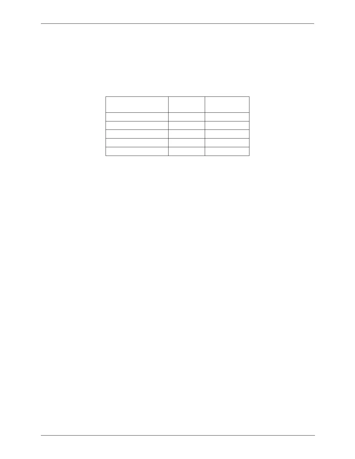
bad. Several of the control devices are in sockets and can be easily replaced. The
table below lists the control device associated with a particular function.
Table 8-8: Relay PCA Control Devices
PHOTOMETER O
3
GENERATOR PRESSURE /FLOW SENSOR 8.4.8.
ASSEMBLY
This assembly is only present in calibrators with O
3
generator and/or photometer
installed. The pressure/flow sensor PCA, located at the rear of the instrument
between the O
3
generator and the photometer pump (see Figure 3-5 for T703; see
Figure 3-7 for T703U) can be checked with a Voltmeter. The following
procedure assumes that the wiring is intact and that the motherboard as well as
the power supplies are operating properly:
BASIC PCA OPERATION:
Measure the voltage across C1; it should be 10 VDC ± 0.25 VDC. If not then
the board is bad.
Measure the voltage between TP2 and TP1 C1; it should be 10 VDC ± 0.25
VDC. If not then the board is bad.
Measure the voltage across C2; it should be 5 VDC ± 0.25 VDC. If not then
the board is bad.